Sun path diagrams can tell you a lot about how the sun will impact your site and building throughout the year. Stereographic sun path diagrams can be used to read the solar azimuth and altitude for a given location. Sun path finder is a device that helps you to read the Stereographic Sun Path Diagrams ans shading analysis.
Azimuth Lines - Azimuth angles run around the edge of the diagram.
Altitude Lines - Altitude angles are represented as concentric circular dotted lines that run from the centre of the diagram out.
Date Lines - Date lines start on the eastern side of the graph and run to the western side and represent the path of the sun on one particular day of the year.
Hour Lines - Hour lines are shown as figure-eight-type lines that intersect the date lines and represent the position of the sun at a specific hour of the day. The intersection points between date and hour lines give the position of the sun.
Step by Step Guide to use Sun Path Finder:
1.Locate the required hour line on the diagram.
2.Locate the required date line, remembering that solid are used for Jan-June and dotted lines for July-Dec.
3.Find the intersection point of the hour and date lines. Remember to intersect solid with solid and dotted with dotted lines.
4.Draw a line from the very centre of the diagram, through the intersection point, out to the perimeter of the diagram.
5.Read the azimuth as an angle taken clockwise from north. In this case, the value is about 62°.
6.Trace a concentric circle around from the intersection point to the vertical north axis, on which is displayed the altitude angles.
7.Interpolate between the concentric circle lines to find the altitude. In this case the intersection point sits exactly on the 30° line.
8.This gives the position of the sun, fully defined as an azimuth and altitude.
A battery management system (BMS) is an electronic system that controls the charging and discharging of a rechargeable battery (cell or battery pack) by protecting the battery from operating outside its safe operating area monitoring its state, calculating secondary data, reporting that data, controlling its environment, and balancing it.
Basic Features of BMS:
Overcharge Protection: Protects the cells as well as the battery from overcharding beyond its safe limit.
Deep Discharge Protection: Protects the cells as well as the battery from deep discharding while powering a load.
Cell Balancing: When a cell is fully charged bypass that cell to let the other cells to be charged.
Types of BMS depend upon the type of cells as well as the number of cells in series. As per the number of cells in series, BMS is classified as
1S: Only one cell
2S: 2 number cells in series
3S: 3 number cells in series
and so on...
The voltage of BMS depends upon the cell type like for Li-Ion 1S BMS its rated voltage is 3.7V. For 2S it would be 7.4V. On the other hand for lithium ferro-phosphate cell (LiFePO4), 1S BMS would be 3.2V and 2S would be 6.4V, and so on...
Every BMS has it's terminal marked connection needs to be done as per marking.
For this lithium ferro-phosphate 1S BMS B- Terminal is for Battery Negative B+ Terminal is for Battery Positive P+ is for Power Positive P- is for Power Negative
B+ and B- connects with the battery and P+ and P- go to the load or charger.
For the above Round type Li-Ion BMS also B+ and B- connects with the battery and P+ and P- go to the load or charger.
This lithium ferro-phosphate 2S BMS has five terminals apart from B+, B-, P+, P- it has one extra terminal that is BM. This BM terminal goes to the middle terminal of the battery series.
The Li-Ion 2S BMS also has the same pin configuration.
For 3S Li-Ion BMS, the Connection diagram is shown above. The lithium ferro-phosphate does not come with a 3S configuration.
Instead lithium ferro-phosphate BMS comes with 4S configuration. The connection diagram is shown.
A voltage spike is a transient event, typically lasting 1 to 30 microseconds, that may reach over 1,000 volts. Lightning that hits a power line can give a spike of over 100,000 volts and can burn through wiring insulation and cause fires, but even modest spikes can destroy a wide variety of electronic devices, computers, battery chargers, modems and TVs etc, that happen to be plugged in at the time. However, lightning and utility power anomalies only account for 20% of transient surges. The remaining 80% of surge activity is produced internally. Although these surges may be smaller in magnitude, they occur more frequently and with continuous exposure can degrade sensitive electronic equipment within the facility.
A Surge Protector or a spike suppressor, surge suppressor, surge diverter, Surge Protection Device (SPD) or transient voltage surge suppressor (TVSS) is an appliance or device intended to protect electrical devices from voltage spikes in alternating current (AC) circuits.
Typically the surge device will trigger at a set voltage, around 3 to 4 times the mains voltage, and divert the current to earth. Some devices may absorb the spike and release it as heat. They are generally rated according to the amount of energy in joules they can absorb.
There are three types of power surge protectors:
• Type I: This Power surge protector is installed at the origin such as the main distribution board.
• Type II: It is installed sub-distribution boards.
• Type III: This power surge protector is installed at the protection load.
In our previous blog, we interfaced Pulse-Oximeter (Max30100) Module to NodeMCU. With a little bit of modification that can be upgraded to a full functioning Pulse-Oximeter. We have interfaced 0.96" I2C OLED display before. Today we made a Pulse-Oximeter using that knowledge.
Connection Diagram: Now follow the diagram below to do the connections.
After the connection is done upload the code below.
Source Code:
Video: Watch the video for a better understanding.
Reference:
[1] Sarkar, S., Ghosh, A., Chakraborty, M., & Mondal, A. (2024). Design, Hardware Implementation of a Domestic Pulse Oximeter Using IOT for COVID – 19 Patient. International Journal of Microsystems and Iot, 2(1), 469–475. https://doi.org/10.5281/zenodo.10629635
This LCD device is mainly used in Arduino but it can be connected with any 3.3V controller. These LCDs are used in Nokia 3110/5110 cell phones. It is a very cheap monochrome LCD module made of 84 x 48 pixels. It can be used to display graphics and text together. This display is based on the PCD8544 driver.
Pin configuration of this device is almost like the 16x2 LCD module only instead of 8 data pins one serial data in (Din) pin and one clock (Clk) are there. The list of the pins and their description are listed below.
RST: Pin type active low, so 0V Resets the LCD
CE: Cheap Enable is used to enable the device before sending anything to the LCD
DC: Data/Command is used to select between Rata Register or Command Register
DIN: Data In is used to send information serially to the display. It could be Data or Command
CLK: Clock is used to synchronize the display with the controller
VCC: To power, the pin 5V or 3.3V is applied here
BL: This pin is used to power the Backlight of the display
In the code below we have displayed text, then we have displayed the same text in inverted mode, after that we have rotated the text finally we displayed the ASCII table. Source Code 1:
Video 1:
Here in the second code, we tested display by displaying an image. To display the image we have to convert the image into code. To do that open the link image2cpp. Link: http://javl.github.io/image2cpp/
Go to "Choose Files" and select the file from your computer.
Select the "Canvas Size" to 84x48 and "Scaling" as Scale to fit. Then check the preview to make sure everything is alright.
Now select the "Code Output Format" to "Arduino code" and click on "Generate code"
Finally copy the code and add that to the code below to display an image of your own.
The MAX30100 has integrated pulse oximetry and heart-rate monitor sensor integrated circuit with I2C interface. NodeMCU is mostly preferred as it is a 3.3V controller.
Components Required:
Pulse Oximeter MAX30100
NodeMCU
Jumper Wires
Bread Board
Soldering Kit (Optional)
Before the connection is done there is slight modification needs to be done. The board shown above has little issue with NodeMCU or any other controller. As the NodeMCU is a 3.3V controller it sends or receives I2C signals at a 3.3V logic level. MAX30100 usually comes with its I2C bus pulled up to 1.8V. This is why if you don't make any modifications, the code might not run. Although without modification, you would be able to check its I2C address but rest of the functions won't work.
Now before we go for the modification let's see the Pinout of MAX30100. It has 14 pins. The I2C bus is at Pin 2 and Pin 3 is SCL and SDA. Pin 13 is for INT (Interrupt), Pin 11 and 12 is for Power and Ground.
If we look at the module we will be able to find that Pin 2(SCL), Pin 3(SDA), Pin 5(IR_DRV), Pin 6(R_DRV), Pin 13(INT) are connected to the header. Pin 9(R_LED+) and Pin 10(IR_LED+) are connected to 3.3V. Pin 11(VDD) is connected to 1.8V. Pin12(GND), Pin4(PGND) are connected to the ground.
Above the red marked 3 pin device is a 1.8V regulator supplying 1.8V to VDD (Pin 11) and also to the three 4.7k Ohms pull-up resistors.
Here we have three 4.7k Ohm resistor pulling up Pin 2(SCL), Pin 3(SDA), Pin 13(INT) up to 1.8V. Here we have to make a change and we have to pull these pins up to 3.3V to connect them with NodeMCU. This could be done in two ways.
Option 1: Remove them and connect 3 external 4.7k Pull up Resistors for 3.3V.
Option 2: Without removing them we will use them by making a slight change in the module. To do that at first with a help of a sharp cutter we will disconnect them from the 1.8V pin of the regulator. Just make a cut at the Red marked position shown in the image below. To make sure the disconnection is complete check continuity using a Multimeter. Do it carefully so that no damage happens at any other part of the device.
Then Connect the points shown below. Make sure during soldering no other points get connected.
If the above step is difficult for you then you can connect these two. Both the pins are 3.3V so they won't make any difference.
For me the first option was easier so after mofification my module looks like this.
Reference: [1] Sarkar, S., Ghosh, A., Chakraborty, M., & Mondal, A. (2024). Design, Hardware Implementation of a Domestic Pulse Oximeter Using IOT for COVID – 19 Patient. International Journal of Microsystems and Iot, 2(1), 469–475. https://doi.org/10.5281/zenodo.10629635
Light Intensity is an important parameter. This could be measured by various components (eg. LDR) with proper calibration. This is why BH1750 is easy to use. It has an I2C interface so data could be extracted easily using the I2C Bus.
Things we need:
BH1750
Arduino
Jumper Wires
Bread Board (Optional)
Connection Diagram:
Connection is very simple, BH1750 has five pins Vcc, Gnd, SCL, SDA, Addr. Connect the pins accordingly.
VCC pin to Arduino 5V
GND pin to Arduino Ground
SCL pin to Arduino A5
SDA pin to Arduino A4
Once the connection is done open Arduino IDE and upload the code below.
In our previous blog, we discussed interfacing of Dot Matrix Display with Arduino and found out that the process consumes lots of Arduino pins. To solve this issue we will use a driver IC. With help of this driver IC, we will control an 8x8 Dot Matrix Display using only 3 I/O pins.
The module has five pins. Their descriptions are given below.
VCC - 5V GND - Ground DIN - Data In
CS - Chip Select CLK - Clock
Materials Required:
Dot Matrix Display Module
Jumper Wires
Arduino
Circuit Diagram:
VCC pin to Arduino 5V pin
GND pin to Arduino GND pin
DIN pin to Arduino Pin 11
CS pin to Arduino Pin 7
CLK pin to Arduino Pin 13
Connect the display module with Arduino as shown above. After the connection is complete then upload the program. You should find the result as shown in the below video.
Source Code:
In this second version, the array is introduced. Using array we can store multiple values in a variable. This allows us to make the code short. If you go through the resulting video you will find that this second version is more complex sill the code size is less.
Dot Matrix displays are categorized upon their number of rows and number of columns and size of pixels. Usually, dot matrix displays come in the square shape of 8x8 LEDs but here we are going to demonstrate a 7x5 LEDs Display. The benefit of a dot matrix display is that you will be able to display characters or images using this. The process shown here is very simple to understand but the drawback is that this process consumes lots of pins. If you look at the Arduino in the video below you will see that 12 digital I/O pins are used to control one display. For come controllers, we might not have 12 I/O pins at all. The process of overcoming this scenario we will discuss in our next blog.
Things we need:
Arduino
7x5 Dot Matrix Display
330 Ohms - 7 Nos
Dot Vero (KS-100) or Bread Board
Jumper Wires
Soldering Kit (Not required for Bread Board)
Connection Diagram:
Connect the pins as described then upload the code below. The first code is about displaying a heart in portrait mode and the second code is about displaying the same heart in landscape mode. Check the results in the video below.
Seven segment displays come in different sizes. Their pin configuration also varies. So after purchasing any Common Cathode (CC) or Common Anode (CA) type display one must find the pin configuration. Usually, the datasheet could be found using the printed model number on the 7-Segment display. Depending upon the type (CC or CA) drivers are available to drive a display. Otherwise, they require an 8bit data line and 1bit control line per display. Drivers also help to drive the current for segments as sometimes for bigger displays the requirement of the current might be more than the controller could supply.
In a 7 Segment Display, the segments are named as a,b,c,...,e,f, and Dot Point. The segments are positioned as below.
To interface 7-Seg display with Arduino, we need
Arduino UNO / NANO
7-Seg Display Common Anode type
330 Ohms Resistor
40x1 Male Berg Strip
Dot Vero or Bread Board
Connecting Wires
Jumper Wires - Male Female Type
Soldering Kit (Not required for Bread Board)
Connection Diagram:
D2 is connected to A
D3 is connected to B
D4 is connected to C
D5 is connected to D
D6 is connected to E
D7 is connected to F
D8 is connected to G
D9 is connected to Common Pin
Once the connection is complete copy the below code to Arduino IDE and upload it to your Arduino.
The code is for displaying 0-9. After uploading you should see the counting started. Please check the video for results.
Troubleshoot:
If you find that all the segments are not glowing at 8 that means there are some wires that are not connected properly.
If you see that display is showing abnormal values please check the connection diagram between Arduino and the Display.
LEDs are the most basic kind of display. But the problem is One LED has only two states, On state and Off state. So it can not give more than two outputs. If we need more than two outputs what option do we have?
We can use multiple LEDs to make a display. So eight LEDs are combined together to make a display that can show 0-9 and Dot point. To display a digit maximum of seven segments consists of seven LEDs are used. Hence the name came Seven Segment Display. Eight LEDs can be connected in two ways either we could common all of their positive together or the negative together. This is why we have two types of seven-segment displays. Common cathode and common anode. A typical structure and connection diagram of the 7-Segment display is shown below. 0-9 is not enough to display right? What if we need to display characters, symbols, or images?
Dot Matrix displays are the solutions. Multiple LEDs are connected together to form an array. They are connected row-wise cathode and column-wise anode or vice-versa. Now with this formation, we can easily display anything we want. If we use RGB LEDs then displaying colored images also possible. A typical connection diagram and image of the dot matrix display are shown below.
LCD Displays comes in different sizes. These displays are popular because they are easy to interface with. We had already interfaced 16x2 LCD with Arduino Microcontroller in our previous blogLCD Display Interface with Arduino.
There was one drawback. LCD Displays require a minimum of six pins. Most of the microcontroller does not have this much pins to bare. What if we need to interface two LCDs, that would cost twelve pins. To solve this issue we need the I2C Module.
With help of this module, we only need only the I2C bus. The advantage is multiple devices could be connected on one bus.
Things we need:
Arduino Uno
IIC Module for LCD Display
16x2 LCD Display
2mm Pitch 1x40 Female Berg Strip
2mm Pitch 1x40 Male Berg Strip
Connection is simple, First using Berg Strip connect LCD Module with the IIC Module. Then using Jumper wire connect Arduino 5V pin to Modules VCC Pin, Arduino Gnd pin to Module Gnd Pin, Arduino A5 Pin to Modules SCL Pin, and Arduinos A4 Pin to I2C Modules SDA Pin as shown below.
LCD Module can be soldered directly with the IIC Module but this would create a problem if any of the two gets damaged. Otherwise, LCD can be brought together pre-soldered with the IIC Module.
Circuit Diagram:
After the connection is complete copy-paste and upload, the I2C scanner code. Then open the Serial Monitor there you will find the I2C address for your device. Note the IIC address.
I2C Scanner:
Now Copy the code below to your Arduino IDE and Replace my IIC address (0x3F) with your IIC address that you noted ago. Then upload the code. And you should see the screen working. If nothing on the screen try to rotate the Potentiometer that you have on the IIC Module. That pot controls the Contrast of your display.
Value Display Widget is another widget that we are going to use today. It is used to display values. We are going to monitor Temperature and Humidity using this widget.
In our previous blog, we have interfaced the DHT22 Sensor with Arduino. Now in this blog, we send data to Blynk so that we could monitor it over IoT.
If you are doing it for the first time please follow DHT Sensor Interfacing for getting an idea over DHT22
DHT 22 has a one-wire interface. In this project, we have connected DHT22 in the D2 pin of NodeMCU. Virtual Pin V1 and V2 are used for the Value Display Widgets.
For this project, we need
NodeMCU
DHT22
Jumper Wires
Blynk App
Add two Value Display Widgets, named as Temperature and Humidity. Set the Inputs as V1 for Humidity and V2 for Temperature as shown below.
Now open the IDE copy-paste the code. Carefully delete YourAuthToken and paste your auth code there. Then delete YourNetworkNameand write your WiFi router or phone's hotspot name there. Finally, delete YourPassword and put your Wi-Fi or hotspot password. Then you can upload the code. Once uploaded your NodeMCU should get connected to your WiFi network.
Relay is a switch that can be actuated using an electrical signal. In this blog, we will discuss the operation of a relay and relay board along with the process of interfacing with different microcontrollers. There are many types of relays. We will discuss SPDT type. An SPDT relay has five terminals Normally Open (NO), Normally Close (NC), Common (C), A1 and A2 are used to power the coil. When the coil is powered contact between C and NC switches to NO side, this is called actuated state.
Relays are used when we are using electrically isolated circuits. Like using a 5V DC Relay we can turn on 230V AC load.
Things we need
SPDT Relay 5V (RL1)
NPN Transistor : BC547 (Q1)
Resistor : 1k Ohm (R1)
Diode : 1N4007 (D1)
LED Optional
In our project we can connect any micronontroller's pin at Input. 1k Ohm resistor is used to control the base current of the transistor Q1. D1 is a Freewheeling Diode. RL1 is the relay that is controlling the 12V Load.
Before we controlled the Led Widget of the Blynk app. Now we will learn about the Button Widget and see how to change the circuit diagram so that we could control large electrical loads. This is a basic Home Automation Project.
For this project we need
NodeMCU
Blynk App Installed in a Android Phone
Relay Board
LED as Load
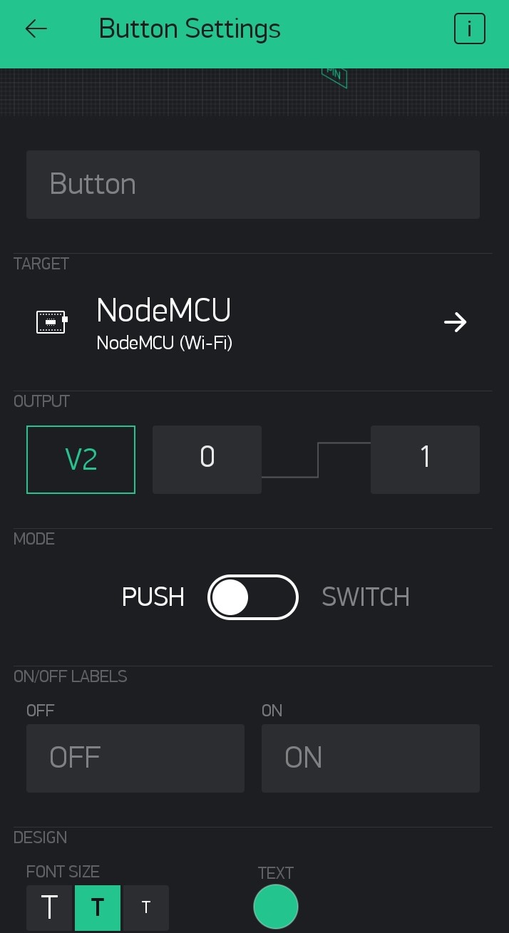
Please follow the Step by Step Blynk Installation Guide to install the Blynk app on your phone. Then add the Button Widget and LED Widget (optional). Then tap on the Button Widget and make V2 as the output as in the image below.
Then tap on the LED Widget and change V1 as the Input.
Then connect your node MCU to your desktop or laptop. If you are using NodeMCU for the first time then you have to add Node MCU to your Arduino IDE. Please follow the step-by-step tutorial for Programming NodeMCU Step by Step Using Arduino IDE.
Now open the IDE copy-paste the code. Carefully delete YourAuthToken and paste your auth code there. Then delete YourNetworkNameand write your WiFi router or phone's hotspot name there. Finally, delete YourPassword and put your Wi-Fi or hotspot password. Then you can upload the code. Once uploaded your NodeMCU should get connected to your WiFi network.
Now if you tap on the Play at the top right corner the icon would turn to Stopand you will be able to see your device online.
Now use the Button on the Blynk app to control the LED on NodeMCU.
The LED on the NodeMCU is connected to the GPIO2 or D4 pin of your NodeMCU. So if you connect a relay board at GPIO2 you will be able to control the relay also. The operation of the relay board will be discussed later on another blog.


 This lithium ferro-phosphate 2S BMS has five terminals apart from B+, B-, P+, P- it has one extra terminal that is BM. This BM terminal goes to the middle terminal of the battery series.
 For 3S Li-Ion BMS, the Connection diagram is shown above. The lithium ferro-phosphate does not come with a 3S configuration.