Showing posts with label IoT. Show all posts

April 28, 2021

IoT Using Blynk - Temperature and Humidity Monitoring

Value Display Widget is another widget that we are going to use today. It is used to display values. We are going to monitor Temperature and Humidity using this widget.

In our previous blog, we have interfaced the DHT22 Sensor with Arduino. Now in this blog, we send data to Blynk so that we could monitor it over IoT.

DHT 22 has a one-wire interface. In this project, we have connected DHT22 in the D2 pin of NodeMCU. Virtual Pin V1 and V2 are used for the Value Display Widgets. 

For this project, we need

  • NodeMCU
  • DHT22
  • Jumper Wires
  • Blynk App

 Add two Value Display Widgets, named as Temperature and Humidity. Set the Inputs as V1 for Humidity and V2 for Temperature as shown below.


Now open the IDE copy-paste the code. Carefully delete YourAuthToken and paste your auth code there. Then delete YourNetworkName and write your WiFi router or phone's hotspot name there. Finally, delete YourPassword and put your Wi-Fi or hotspot password. Then you can upload the code. Once uploaded your NodeMCU should get connected to your WiFi network.

Source Code:

Results:


February 13, 2021

IoT Using Blynk - Controlling Load using Push Button Widget

Before we controlled the Led Widget of the Blynk app. Now we will learn about the Button Widget and see how to change the circuit diagram so that we could control large electrical loads. This is a basic Home Automation Project.

For this project we need 

  • NodeMCU 

  •  Blynk App Installed in a Android Phone 

  •  Relay Board

  •  LED as Load

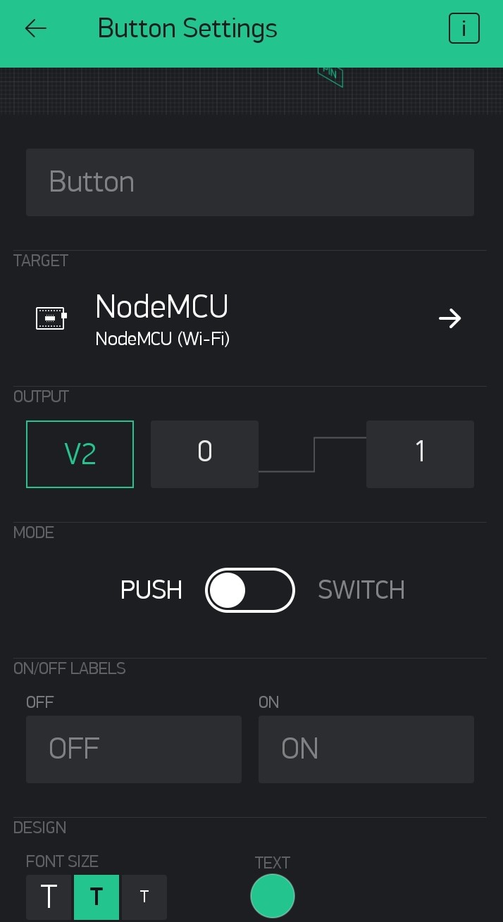
Please follow the Step by Step Blynk Installation Guide to install the Blynk app on your phone. Then add the Button Widget and LED Widget (optional). Then tap on the Button Widget and make V2 as the output as in the image below. 

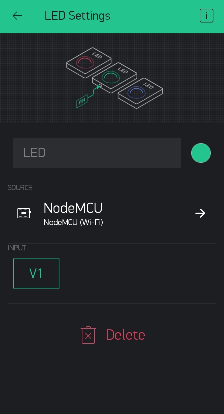
Then tap on the LED Widget and change V1 as the Input.


Then connect your node MCU to your desktop or laptop. If you are using NodeMCU for the first time then you have to add Node MCU to your Arduino IDE. Please follow the step-by-step tutorial for Programming NodeMCU Step by Step Using Arduino IDE.

Now open the IDE copy-paste the code. Carefully delete YourAuthToken and paste your auth code there. Then delete YourNetworkName and write your WiFi router or phone's hotspot name there. Finally, delete YourPassword and put your Wi-Fi or hotspot password. Then you can upload the code. Once uploaded your NodeMCU should get connected to your WiFi network.

Now if you tap on the Play at the top right corner the icon would turn to Stopand you will be able to see your device online.

Now use the Button on the Blynk app to control the LED on NodeMCU. 

The LED on the NodeMCU is connected to the GPIO2 or D4 pin of your NodeMCU. So if you connect a relay board at GPIO2 you will be able to control the relay also. The operation of the relay board will be discussed later on another blog.

Source Code:

Video:

January 09, 2021

IoT Using Blynk - Blinking LED Widget

We already blinked the built-in LED of NodeMCU. We have also discussed the Blynk App, how to install and set it up. Now we will go for the Led of Blynk app. These Widgets act as virtual hardware. Our Aim is to blink the Virtual LED with the actual LED in NodeMCU.

If you are new then follow the Step by Step Blynk Installation Guide to install the Blynk app on your phone. If you are using NodeMCU for the first time then you have to add NodeMCU to your Arduino IDE. Please follow the step-by-step tutorial for Programming NodeMCU Step by Step Using Arduino IDE.

In our last blog, we got a mail from Blynk which has Auth Token. This Auth Token is a unique identifier that is particularly dedicated to a controller or hardwire. Think of it as your identity number of the NodeMCU. With this ID number, Blynk identifies your controller and differentiates it from all other controllers that are running by others all around the globe.

For this project, we will only need 

  • NodeMCU 

  •  Blynk App Installed in a Android Phone 

Step 1: Open Arduino IDE.


Step 2: Copy-Paste the code there.


Step 3: Copy the Auth-Code that is sent to your mail-id. Just delete YourAuthToken and paste your auth code there. Then delete YourNetworkName and write your WiFi router or phones hotspot name there. Finally, delete YourPassword and put your Wi-Fi or hotspot password.

Step 4: Click on Tools and make sure that you have selected the right device and the right port. For me its NodeMCU and COM11. (For you it may not be COM11 so check before uploading)

Step 5: Finally, save the code and hit the upload button. 

Then go to the settings of the LED Widget. You can do it by tapping on the LED widget. Set V1 as the Input.


Video: IoT Using NodeMCU and Blynk

Source Code:


January 08, 2021

Blynk

Blynk is a free IoT platform. Let's set up Blynk step by step.

Step 1: Open play store, search for the app Blynk and install the app.


Step 2: Install the app in your device.

Step 3: Find the app icon looks like the one shown below. Then open it.

Step 4: If you have an account log in otherwise click on Create New Account. You can log in using your Facebook account also.

Step 5: Enter your email id and then create a password and enter it. Note that this is not your email id's password. You have to create a different password.

Step 6: Click Sign Up

Step 7: Read the note and Click on Cool! Got it. This service is not totally free but partially free. We will discuss it later.

Step 8: Now its time to make a new project. Click on New Project.

Step 9: Click Project Name to edit it and give it a new name.

Step 10: In my case, I've chosen Test Project.

Step 11: Then Click the drop-down menu and find the controller you are using and select OK. In my case, I have chosen NodeMCU because in my last blog was about programming NodeMCU.

Step 12: Select Connection Type as Wi-Fi and click Create.

Step 13: Click ok and find the Auth token from your email id. We will discuss this Auth Token and how to use it in our next blog. 


Step 14: This is a blank project. Now you have to add some widgets. Now, these widgets are not free. You get only 2000 Units of energy and this energy you have spent to get a widget. The declaration in Step 7 was about this.

Step 15: There are various types of widgets and all have prise. So choose your weapon wisely.

I'll discuss some of these widgets later in another blog.


September 04, 2020

Pyranometer

 A pyranometer is a type of actinometer used for measuring solar irradiance on a planar surface and it is designed to measure the solar radiation flux density (W/m2) from the hemisphere above within a wavelength range of 400 nm to 1000 nm(range may vary upon application).

Types of Pyranometer:
Pyranometers can be recognized and grouped into two different technologies: Thermopile Technology and Silicon Semiconductor Technology.

Thermopile Pyranometers:
It has a thermopile detector (a device that converts thermal energy into electrical energy) with strongly light-absorbing black paint that equally consumes all sun radiation. This creates a temperature difference between the black surface of the sensors and the body of the instrument and results in a small voltage at the sensor that can be measured and translated into W/m2.
Thermopile pyranometers follow the ISO 9060 standard, also adopted by the World Meteorological Organization (WMO). This standard discriminates between three classes. The latest version of ISO 9060, from 2018 uses the following classification: Class A for the best performing, followed by Class B and Class C, while the older ISO 9060 standard from 1990 used ambiguous terms such as "secondary standard", "first-class", and "second-class".


Semiconductor Pyranometers:
A semiconductor or silicon pyranometer uses a photodiode (a device that converts light into current) to create an electrical signal from the incoming solar radiation. It can detect the portion of the solar spectrum between 400 nm and 1100 nm.


    The device measures radiation from the sun and the sky on a horizontal surface. When exposed to radiation, the silicon cell produces a voltage, and the current output is proportional to the radiation energy received. 

    Now, this signal is sent to a device that converts this signal to a human-readable format. This device can be a data logger or a display unit.


To know more about data loggers follow the link below.
https://creativestudio1973.blogspot.com/2020/09/datalogger.html

Reference:

  1. https://en.wikipedia.org/wiki/Pyranometer
  2. https://www.eko-instruments.com/us/categories/products/pyranometers


Datalogger

A data logger is an electronic device that records data over time with a built-in or via external sensors.