In this project, we will introduce you to the HC-SR04 Ultrasonic sensor. It works by sending sound waves from the transmitter, which then bounce off of an object and then return to the receiver. You can determine how far away something is by the time it takes for the sound waves to get back to the sensor. Let's get right to it!
This project is about the interfacing of an Ultrasonic Sensor module with Arduino UNO. This Project could measure the distance from a 2-400cm distance by using sound wave at 40000hz.
Components Required:
1.Arduino Uno
2.HC-SR04 Ultrasonic module
3.Data Cable
4.Jumper wires
How Ultrasonic sensor works?
First, the transmitter sends an ultrasonic wave that reflects from an abject nearby. When the sound waves hit the receiver, it turns the Echo pin high for however long the waves were traveling for. To get that, we can use a handy Arduino function called pulseIn(). It takes 2 arguments, the pin you are listening to(In our case, the Echo pin), and a state(HIGH or LOW). What the function does is waits for the pin to go whichever state you put in, starts timing, and then stops timing when it switches to the other state. In our case, we would put HIGH since we want to start timing when the Echo pin goes high. We will store the time in the duration variable. (It returns the time in microseconds)
Now that we have the time, we can use the equation speed = distance/time, but we will make it time x speed = distance because we have the speed. What speed do we have? The speed of sound, of course! The speed of sound is approximately 340 meters per second, but since the pulseIn() function returns the time in microseconds, we will need to have a speed in microseconds also, which is easy to get. A quick Google search for "speed of sound in centimeters per microsecond" will say that it is .0343 c/μS. You could do the math, but searching for it is easier. Anyway, with that information, we can calculate the distance! Just multiply the duration by .0343 and then divide it by 2 (Because the sound waves travel to the object AND back). We will store that in the distance variable.
How To Use?
In order to generate the ultrasound, you need to set the Trig on a High State for 10 µs. That will send out an 8 cycle sonic burst which will travel at the speed sound and it will be received in the Echo pin. The Echo pin will output the time in microseconds the sound wave traveled. But what you will get from the Echo pin will be double that number because the sound wave needs to travel forward and bounce backward. So in order to get the distance in cm, we need to multiply the received travel time value from the echo pin with the velocity of sound and divide it by 2.
distance = (velocity of sound x time)/2
velocity of sound = 0343 cm/μS;
Pinout:
VCC supplies power for the module. You can directly connect it to the 5V pin on the Arduino.
GND is the Ground Pin and needs to be connected to the GND pin on the Arduino.
Trig
Echo
HC-SR04-sensor-library
coming soon Functions under this library
coming soon
There are many ways to do this project here we are going to discuss how to do this project using LM3914 IC.
Components Required
LM3914 - 1Nos
Potentiometer 5k - 1Nos
LEDs - 10Nos
Resistor
1k - 1Nos
2.2k - 1Nos
Vero Board - 1Nos
Connecting Wires
In the Battery Voltage Level Detector, the heart of the project is the ic LM3914. It's an ic that can drive 10 LEDs. With increasing the input signal voltage the ic turns LEDs one by one to indicate the charge level. Follow the diagram and connect the circuit diagram accordingly.
Chaser could be made by various ways we are here discussing how to make chaser led using the 4017 IC.
Components Required:
4017 IC - 1Nos
555 IC - 1Nos
LEDs - 10Nos
Resistor
2.2k - 1Nos
18k - 1Nos
Potentiometer 100k - 1Nos
Capacitor 1uF/50V - 1Nos
Vero Board - 1Nos
4017 IC is a 16pic ic that can drive 10 LEDs. To make a chaser you have to follow the connection diagram shown here.
The Whole circuit has two parts. In the right section, there is one 555 Timer IC which is in an astable mode where it is generating clock pulses.
On the left side, IC 4017 is driving 10 LEDs and using that clock pulse changing the position of the light one by one.
In this post, we are going to discuss OLED display interfacing with Arduino as it is very important to interfacing with an output device to view the output from a controller.
Components Required:
1. Arduino Uno
2. OLED Display ( 0.96" )
3. Bread Board ( not necessary )
4. Jumper Wires
5. Data Cables
What is OLED Display?
An organic light-emitting diode (OLED or Organic LED), also known as an organic EL (organic electroluminescent) diode, is a light-emitting diode (LED) in which the emissiveelectroluminescent layer is a film of organic compound that emits light in response to an electric current. This organic layer is situated between two electrodes; typically, at least one of these electrodes is transparent. OLEDs are used to create digital displays in devices such as television screens, computer monitors, portable systems such as smartphones, handheld game consoles, and PDAs. An OLED display works without a backlight because it emits visible light. Thus, it can display deep black levels and can be thinner and lighter than a liquid crystal display (LCD). In low ambient light conditions (such as a darkroom), an OLED screen can achieve a higher contrast ratio than an LCD, regardless of whether the LCD uses cold cathode fluorescent lamps or an LED backlight. Pinout:
VCC: OLED Display runs on 3.3V. It can be powered by Arduino UNO but an external power supply is safe.
GND: Goes to any ground pin.
SDA: Serial Data pin transmits the data ar receives the data.
SCL: Serial Clock pin in I2C communication usually sends the clock pulse.
How To Interface?
Arduino has SDA and SCL pin inbuilt, for the I2C device interface externally. Arduino Pin A4 and A5 are used for I2C where A4 SDA is A5 is SCL. Just connect the pin accordingly and upload the code in the Arduino.
Arduino Pin OLED Pin
3.3V -------------- VCC
GND -------------- GND
A5 ----------------- SCL
A4 ----------------- SDA
Be careful! do the wiring accordingly, double-check the wiring before powering the circuit and watch the video link below to get an idea about the project.
Now here is a twist. Using I2C Communication we could connect more than one device using only those two ( SDA, SCL ) wires, now How the controller supposed to know from which device it is getting a data or How the device supposed to know which data to pick up. Here comes the address of devices. Each and every device comes with a unique address.
To interface the OLED Display you have to find its address and send the data to that address so that the display picks up that data.
To find the address of the Display upload the code below. Once you get the address copy the address and put it in the main code and you are ready.
This project is about the interfacing of a DHT22 module with Arduino UNO. The data for temperature and humidity are displayed on the Serial Terminal.
Components Required:
1.Arduino Uno
2.DHT22 Module
3.Data Cable
4.Jumper wires
What is DHT Sensor?
DHT11 and DHT22 sensors are very basic and slow but are great for hobbyists who want to do some basic data logging. The DHT sensors are made of two parts, a capacitive humidity sensor, and a thermistor. There is also a very basic chip inside that does some analog to digital conversion and spits out a digital signal with the temperature and humidity. The digital signal is fairly easy to read using any microcontroller.
DHT11 vs DHT22:
There are two versions of the DHT sensor, they look a bit similar and have the same pinout, but have different characteristics. Here are the specs:
DHT11:
Ultra-low-cost
3 to 5V power and I/O
2.5mA max current use during conversion (while requesting data)
Good for 20-80% humidity readings with 5% accuracy
Good for 0-50°C temperature readings ±2°C accuracy
No more than 1 Hz sampling rate (once every second)
Body size 15.5mm x 12mm x 5.5mm
4 pins with 0.1" spacing
DHT22:
Low cost
3 to 5V power and I/O
2.5mA max current use during conversion (while requesting data)
Good for 0-100% humidity readings with 2-5% accuracy
Good for -40 to 80°C temperature readings ±0.5°C accuracy
No more than 0.5 Hz sampling rate (once every 2 seconds)
Body size 15.1mm x 25mm x 7.7mm
4 pins with 0.1" spacing
As you can see, the DHT22 is a little more accurate and good over a slightly larger range. Both use a single digital pin and are 'sluggish' in that you can't query them more than once every second or two.
Pinout:
VCC supplies power for the module. You can directly connect it to the 5V pin on the Arduino.
Data pin transmits the temperature and humidity data in digital form.
GND is the Ground Pin and needs to be connected to the GND pin on the Arduino.
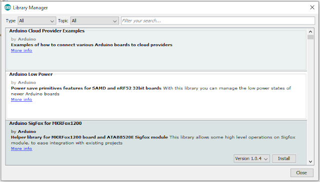
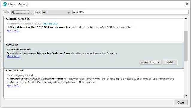
Sometimes there are components that we interface with Arduino that require a special set of codes that we need to install in our IDE to run the program. Library Manager is used for installing these libraries. They contain the information for header files that we include in our code. Usually, IDE comes with a set of pre-installed libraries although they were not enough. To install these libraries follow the steps below.
Step 1: Open Arduino IDE
Step 2: Go to Tools
Step 3: Click on Manage Libraries
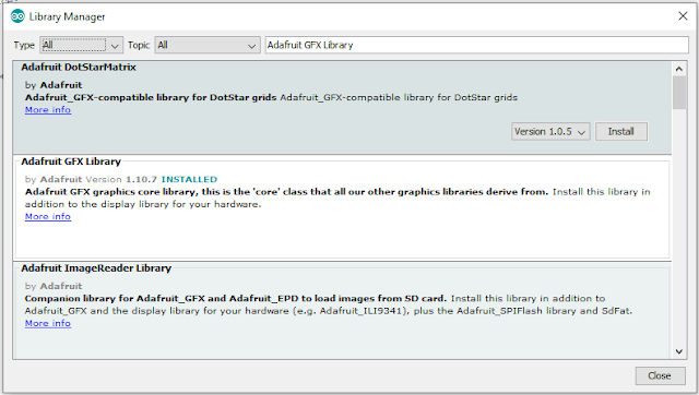
Step 4: This is the Library Manager, from where libraries could be installed
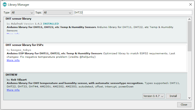
Step 5: To install DHT 22 Library select the library click on Install. Before installing you can even select the version of the library before installing
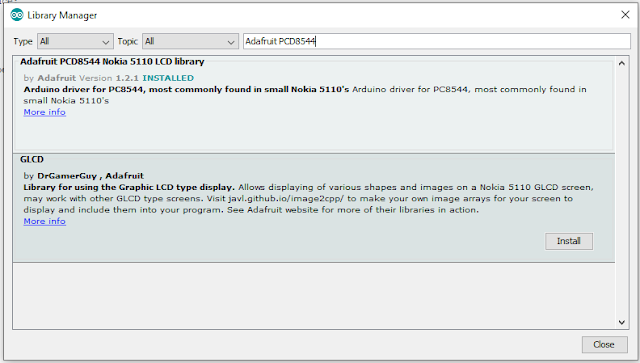
Here are some libraries that we will use in our future projects...
Adafruit PCD8544 library is used for Nokia 5110 LCD Display
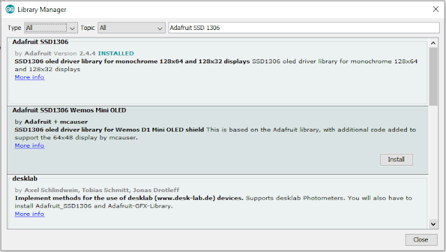
Adafruit SSD1306 library is used for OLED Display
Adafruit GFX Library is used for Adafruit display.
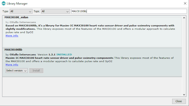
MAX30100lib Library is used for MAX30100 Pulse Oximeter
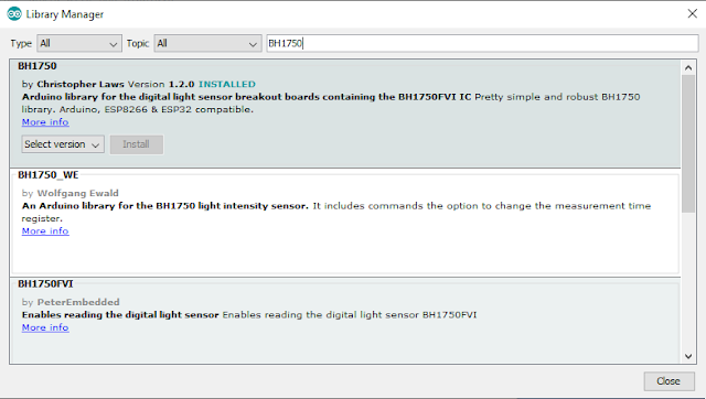
MAX30100lib Library is used for BH1750 Light Intensity Sensor
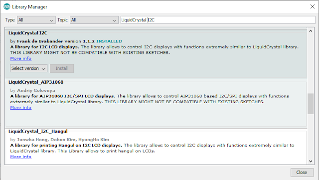
LiquidCrystal I2C Library is used for IIC based LCD Module
Adafruit ADXL345 Library is used for 3-axis Accelerometer Interfacing
This project is about the interfacing of
a GPS module with Arduino UNO. The data for longitude, latitude with date and
time is displayed on Serial Terminal.
Components Required:
1.Arduino Uno
2.Ublox NEO-6m GPS module
3.Data Cable
4.Jumper wires
Now, What is GPS?
The Global Positioning System (GPS) is a satellite-based navigation system made
up of at least 24 satellites. GPS works in any weather condition, anywhere in
the world, 24 hours a day, with no subscription fees or setup charges.
How GPS works?
GPS satellites circle the Earth twice a day in a precise orbit. Each
satellite transmits a unique signal and orbital parameters that allow GPS
devices to decode and compute the precise location of the satellite. GPS receivers
use this information and trilateration to calculate a user's exact location.
Essentially, the GPS receiver measures the distance to each satellite by the
amount of time it takes to receive a transmitted signal. With distance
measurements from a few more satellites, the receiver can determine a user's
position and display it.
To calculate your 2-D position (latitude and longitude) and track
movement, a GPS receiver must be locked on to the signal of at least 3
satellites. With 4 or more satellites in view, the receiver can determine your
3-D position (latitude, longitude, and altitude). Generally, a GPS receiver
will track 8 or more satellites, but that depends on the time of day and where
you are on the earth.
Once your position has been determined, the GPS unit can calculate other
information, such as:
Speed
Bearing
Track
Trip dist
Distance to destination
What's the signal?
GPS satellites transmit at least 2 low-power radio signals. The signals
travel by line of sight, meaning they will pass through clouds, glass, and
plastic but will not go through most solid objects, such as buildings and
mountains. However, modern receivers are more sensitive and can usually track
through houses.
A GPS signal contains 3 different types of information:
·Pseudorandom
code is an I.D. code that identifies which satellite is
transmitting information. You can see which satellites you are getting signals
from on your device's satellite page.
·Ephemeris
data is needed to determine a satellite's position and
gives important information about the health of a satellite, current date and
time.
·Almanac
data tells the GPS receiver where each GPS satellite
should be at any time throughout the day and shows the orbital information for
that satellite and every other satellite in the system.
NEO-6M GPS Module
The NEO-6M GPS module is shown in the figure below. It comes with an
external antenna and does not come with header pins. So you will need to solder
it.
Overview of NEO-6M GPS Module
NEO-6M
GPS Chip:
The heart of the module is a
NEO-6M GPS chip from u-blox. It can track up to 22 satelliteson 50 channels and achieves the industry’s highest level of sensitivity i.e. - 161 dB tracking while consuming only 45mA supply current. The u-blox 6 positioning engine also boasts a Time-To-First-Fix (TTFF) of under 1 second. One of the best features the chip provides is Power Save Mode (PSM). It allows a reduction in system power consumption by selectively switching parts of
the receiver ON and OFF. This dramatically reduces the power consumption of the
module to just 11mA making it suitable for power-sensitive applications like
GPS wristwatch. The necessary data pins of NEO-6M GPS chip are broken out to a
"0.1″ pitch headers. This includes pins required for communication with a
microcontroller over UART.
Note:- The module supports the baud rate from 4800bps to 230400bps with a default baud of 9600.
Position Fix LED Indicator:
There is an LED on the NEO-6M GPS Module which indicates the status of Position Fix. It’ll blink at various rates depending on what state it’s in
No Blinking ==> means It is searching for satellites
Blink every 1s – means Position Fix is found
3.3V LDO Regulator:
The operating voltage of the NEO-6M chip is from 2.7 to 3.6V. But, the module comes with MIC5205 ultra-low dropout 3V3 regulator from MICREL. The logic pins are also 5-volt tolerant, so we can easily connect it to an Arduino or any 5V logic microcontroller without using any logic level converter.
Battery & EEPROM:
The module is equipped with an HK24C32 two-wire serial EEPROM. It is 4KB in size and connected to the NEO-6M chip via I2C. The module also contains a rechargeable button battery which acts as a super-capacitor.
An EEPROM together with a battery helps retain the battery-backed RAM (BBR). The BBR contains clock data, the latest position data (GNSS orbit data), and module configuration. But it is not meant for permanent data storage.
As the battery retains the clock and last position, the time to first fix (TTFF) significantly reduces to 1s. This allows much faster position locks.
Without the battery, the GPS always cold-start so the initial GPS lock takes more time. The battery is automatically charged when power is applied and maintains data for up to two weeks without power.
Pinout:
GND is the Ground Pin and needs to be connected to the GND pin on the Arduino.
TxD (Transmitter) pin is used for serial communication.
RxD (Receiver) pin is used for serial communication.
VCC supplies power for the module. You can directly connect it to the 5V pin on the Arduino.