That's all you have to do. Now let's check what changes have come.
Now lets program nodeMCU with a basic example program Blink. Go to File > Examples > Basic > Blink
Now Go to Tools > Boards: and select NodeMCU
After selecting the board go to Port and select the right communication port. Hit the Upload button.
The upload may take a few seconds and after that, you will find a screen like this stating that uploading is done. During the upload the led near pin D0 might blink several times but after the uploading is complete the led will keep glowing for 1 sec and staying off for 1 second.
NodeMCU is an open-source IoT platform. It includes firmware that runs on the ESP8266 Wi-Fi system on a chip(SoC) from Espressif Systems and hardware which is based on the ESP-12 module. The term "NodeMCU" by default refers to the firmware rather than the development kits. The firmware uses the Lua scripting language. It is based on the eLua project and built on the Espressif Non-OS SDK for ESP8266.
In simple words, NodeMCU is a WiFi-enabled microcontroller. It has a micro USB connector so it could be connected to any computer using data cable. The only thing that you must remember that it is a 3.3V logic level device. It means you will get a 3.3V digital high signal and giving more than 3.3V signal is not safe for the controller, however, the input voltage can vary from 5 to 12V.
NodeMCU Pinout contains 9 Digital pins, 1 Analog Pins, 1 Reset Pins & 4 Power Pins. Although some pins are very difficult to use sometimes. Let's have a look at the pinout.
D0 - D8 are Digital Pins
A0 is the only analog pin
The Micro USB port makes it very easy to connect with PC. Node MCU can be programmed using Arduino IDE but when we program it with Arduino IDE the original Lua firmware gets overwritten or in other words lost.
a
In our next blog, we will discuss the programming process of the NodeMCU.
Pumps are devices that use energy to raise, transport, or compress fluids. Pumps are divided into two main categories, Positive Displacement Pumps and Dynamic Pumps. They also have many types.
Positive Displacement Pump: Pumps in which displacement is accomplished mechanically are called positive displacement pumps. There are many types of Displacement Pumps. a. Diaphragm pumps b. Gear pumps c. Peristaltic pumps d. Cam pumps e. Piston pumps
Dynamic Pump: Kinetic pumps impart kinetic energy to the fluid using a rapidly rotating impeller. There are many types of Dynamic Pumps. a. Centrifugal pumps b. Vertical Pumps
All these types of pumps have their specific pumping fluid nature (i.e. viscosity, density), fluid pressure, and flow rate. Hence their application is also different.
Depending upon the installation locations pumps are of two types, pumps that are installed on the surface and pumps that are submerged under fluid.
Surface Pumps: Surface water pumps A surface water pump helps in pumping out water from a water body, like a well, or a river, and transports it to different destinations.
Submersible Pumps: A submersible pump, also known as an electrical submersible pump, is a water pump that is completely submerged in the water and can be used for a variety of applications. The electric motor used in the process is hermetically sealed and also close-coupled to the pump. One of the major advantages of a submersible pump is that it does not require priming because it has already been submerged in the liquid.
Solar Pumping Systems are nowadays very common. SPV modules are used to run pumps to get water. Depending on These systems come in two types. one with Submersible pumps and one with surface pumps.
Most of the time pumps run with AC power. On the other hand, SPV modules provide us with DC. To integrate them together one VFD-based pump controller is used. Sometimes these controller comes with AC power input terminals, and they can be run using AC Power at night also. They also can be equipped with a float switch so that the pump can be turned on and off depending on the water level of the reserver, tank or borewell.
Variable Frequency Drive: A variable-frequency drive (VFD) is a type of motor drive used in electro-mechanical drive systems to control AC motor speed and torque by varying motor input frequency and, depending on the topology, to control associated voltage or current variation.
There are mainly two types of applications for solar pumping systems.
Solar Pumping for Irrigation where is taken from a borewell by a submersible pump or from a river, lake or pond-like waterbody by a surface pump and used for irrigation.
Solar Pumping System for Drinking Water Project. Where a submersible pump is used to pump groundwater and store it in a tank. Then after filtering the water, it can be used locally. Or using a surface pump it can be pumped to water distribution networks.
Protective Relays: In electrical engineering, a protective relay is a relay device designed to trip a circuit breaker when a fault is detected. The first protective relays were electromagnetic devices, relying on coils operating on moving parts to provide detection of abnormal operating conditions such as over-current, overvoltage, reverse power flow, over-frequency, and under-frequency. Microprocessor-based digital protection relays now emulate the original devices, as well as providing types of protection and supervision impractical with electromechanical relays. Electromechanical relays provide only a rudimentary indication of the location and origin of a fault. In many cases, a single microprocessor relay provides functions that would take two or more electromechanical devices. By combining several functions in one case, numerical relays also save capital cost and maintenance cost over electromechanical relays.
Types according to construction
1. Electromechanical Relay: Electromechanical relays can be classified into several different types as follows: a. Attracted Armature b. Moving Coil c. Induction d. Motor Operated e. Mechanical f. Thermal
2. Induction disc overcurrent Relay: Magnetic system in induction disc overcurrent relays is designed to detect over-currents in a power system and operate with a pre-determined time delay when certain overcurrent limits have been reached. In order to operate, the magnetic system in the relays produces a torque that acts on a metal disc to make contact. "Induction" disk meters work by inducing currents in a disk that is free to rotate; the rotary motion of the disk operates a contact. Induction relays require alternating current; if two or more coils are used, they must be at the same frequency otherwise no net operating force is produced. These electromagnetic relays use the induction principle discovered by Galileo Ferraris in the late 19th century.
3. Static Relay: The application of electronic amplifiers to protective relays was described as early as 1928, using vacuum tube amplifiers, and continued up to 1956. Devices using electron tubes were studied but never applied as commercial products, because of the limitations of vacuum tube amplifiers. A relatively large standby current is required to maintain the tube filament temperature; inconvenient high voltages are required for the circuits, and vacuum tube amplifiers had difficulty with incorrect operation due to noise disturbances. Static relays have no or few moving parts and became practical with the introduction of the transistor. Measuring elements of static relays have been successfully and economically built up from diodes, Zener diodes, avalanche diodes, unijunction transistors, p-n-p, and n-p-n bipolar transistors, field-effect transistors, or their combinations. Static relays offer the advantage of higher sensitivity than purely electromechanical relays because the power to operate output contacts is derived from a separate supply, not from the signal circuits. Static relays eliminated or reduced contact bounce, and could provide fast operation, long life, and low maintenance.
4. Digital Relay: Digital protective relays were in their infancy during the late 1960s. An experimental digital protection system was tested in the lab and in the field in the early 1970s. Unlike the relays mentioned above, digital protective relays have two main parts: hardware and software. The world's first commercially available digital protective relay was introduced to the power industry in 1984 by Schweitzer Engineering Laboratories (SEL) based in Pullman, Washington. In spite of the developments of complex algorithms for implementing protection functions, the microprocessor-based-relays marketed in the 1980s did not incorporate them. A microprocessor-based digital protection relay can replace the functions of many discrete electromechanical instruments. These relays convert voltage and currents to digital form and process the resulting measurements using a microprocessor. The digital relay can emulate functions of many discrete electromechanical relays in one device, simplifying protection design and maintenance. Each digital relay can run self-test routines to confirm its readiness and alarm if a fault is detected. Digital relays can also provide functions such as communications (SCADA) interface, monitoring of contact inputs, metering, waveform analysis, and other useful features. Digital relays can, for example, store multiple sets of protection parameters, which allows the behavior of the relay to be changed during the maintenance of attached equipment. Digital relays also can provide protection strategies impossible to implement with electromechanical relays. This is particularly so in long-distance high voltage or multi-terminal circuits or in lines that are series or shunt compensated. They also offer benefits in self-testing and communication to supervisory control systems.
5. Numerical Relay: The distinction between digital and numerical protection relay rests on points of fine technical detail, and is rarely found in areas other than Protection. Numerical relays are the product of the advances in technology from digital relays. Generally, there are several different types of numerical protection relays. Each type, however, shares a similar architecture, thus enabling designers to build an entire system solution that is based on a relatively small number of flexible components. They use high-speed processors executing appropriate algorithms. Most numerical relays are also multifunctional and have multiple setting groups each often with tens or hundreds of settings.
MCCB: Molded Case Circuit Breaker is a type of electrical protection device which is used when the load current exceeds the limit of a miniature circuit breaker. The MCCB provides protection against overload, short circuit faults and is also used for switching circuits. It can be used for higher current rating and fault levels even in domestic applications. The wide current ratings and high breaking capacity in MCCB find their use in industrial applications. MCCB can be used for the protection of capacitor bank, generator protection, and main electric feeder distribution. It offers adequate protection whenever an application requires discrimination, adjustable overload setting, or earth fault protection.
MCB: Miniature Circuit Breaker automatically switches OFF electrical circuit during any abnormal condition in the electrical network such as overload & short circuit conditions. However, the fuse may sense these conditions but it has to be replaced through MCB can be reset. The MCB is an electromechanical device that guards the electric wires &electrical load against overcurrent so as to avoid any kind of fire or electrical hazards. Handling MCB is quite safer and it quickly restores the supply. When it comes to house applications, MCB is the most preferred choice for overload and short circuit protection. MCB can be reset very fast & doesn’t have any maintenance cost. MCB works on a bi-metal respective principle which provides protection against overload current & solenoid short circuit current.
Types of MCB: It is important to know about the types of MCB trip curves to decide what type to use for different appliances for the correct electrical system. This is the selection chart or the criteria to make a call on one of the MCBs. But before that, it is vital to understand what a trip curve means. Trip curves are essentially nothing but the maximum current that a particular MCB can withstand. Once the ideal current loading is breached, the circuit automatically cuts off.
There are about six different types of MCB, which are A, B, C, D, K, and Z. Firstly, a. Type A, trips off the circuit when the current exceeds 2-3 times the actual current rating. Since this type is highly sensitive to short circuits, it is better suited for semiconductor devices. b. Type B, which trips off when the current flow is 3-5 times the actual flow and finds a use for cable protection. c. The best-suited type of MCB for domestic appliances, where the current load is medium, type C. Type C MCB trips off when the flow of current is 5-10 times more than normal. d. Type D MCB has a high resistance as they can withstand up to 10-20 times the current rate. If you are looking for circuit breakers for devices with a high starting current load like a motor, then type D is the ideal choice. e. The type K MCB withstands up to 8-12 times the initial charge and thus can be used for bulky load devices.
RCCB: Residual Current Circuit Breaker is basically an electrical wiring device that disconnects the circuit whenever there is leakage of current flow through the Human body or the current is not balanced between the phase conductors. It is the safest device to detect and trip against electrical leakage currents, thus ensuring protection against electric shock caused by direct contacts. RCCB is generally used in series with an MCB which protects them from over current and short circuit current. Both phase and neutral wires are connected through an RCCB device. These are an extremely effective form of shock protection & widely used for protection from a leakage current of 30,100 & 300mA. It is essential lifesaving equipment used to protect the human body from electrical and is mandatory in many states for domestic installation.
ELCB: Earth Leakage Circuit Breaker has the same function as RCCB but is a voltage sensor devise. However, this is an old technology & is not in common use. RCCB being a current sensitive device has a better advantage over ELCB.
Contractor: Contractors are electrically controlled switches (relays) used for switching an electrical power circuit. A contactor is typically controlled by a circuit that has a much lower power level than the switched circuit, such as a 24-volt coil electromagnet controlling a 220-volt motor switch.
A pyranometer is a type of actinometer used for measuring solar irradiance on a planar surface and it is designed to measure the solar radiation flux density (W/m2) from the hemisphere above within a wavelength range of 400 nm to 1000 nm(range may vary upon application).
Types of Pyranometer: Pyranometers can be recognized and grouped into two different technologies: Thermopile Technology and Silicon Semiconductor Technology.
Thermopile Pyranometers: It has a thermopile detector (a device that converts thermal energy into electrical energy) with strongly light-absorbing black paint that equally consumes all sun radiation. This creates a temperature difference between the black surface of the sensors and the body of the instrument and results in a small voltage at the sensor that can be measured and translated into W/m2. Thermopile pyranometers follow the ISO 9060 standard, also adopted by the World Meteorological Organization (WMO). This standard discriminates between three classes. The latest version of ISO 9060, from 2018 uses the following classification: Class A for the best performing, followed by Class B and Class C, while the older ISO 9060 standard from 1990 used ambiguous terms such as "secondary standard", "first-class", and "second-class".
Semiconductor Pyranometers: A semiconductor or silicon pyranometer uses a photodiode (a device that converts light into current) to create an electrical signal from the incoming solar radiation. It can detect the portion of the solar spectrum between 400 nm and 1100 nm.
The device measures radiation from the sun and the sky on a horizontal surface. When exposed to radiation, the silicon cell produces a voltage, and the current output is proportional to the radiation energy received.
Now, this signal is sent to a device that converts this signal to a human-readable format. This device can be a data logger or a display unit.
Weather Monitoring Systems are used to keep track of the ever-changing weather conditions. The information obtained by such sensors is used to report weather and maintain track of environmental changes in a given location. Such information is particularly useful in the study of the earth as well as the analysis of changing climatic and environmental conditions in a given location. Furthermore, the collected data and analytics can be used in a range of applications, including agriculture, geology, mining, and building weather forecasting models.
Sensors:
Weather Temperature Sensors: Measures the Temperature the the environment.
Humidity Sensor: Measures the relative humidity of ambient air.
Barometer: It is mainly an Air Pressure Sensor.
Anemometer: It is used to measure Wind Speed.
Wind Vain: Wind Direction is detected by Wind Vain
Rain Gauge: A rain gauge is used to measure the rainfall of an area.
Reference
Mondal, S., Mondal, A., Bhattacharya, S. (2021). Smart Data Logger for Solar and Wind Power Generation. In: Nath, V., Mandal, J.K. (eds) Proceedings of the Fourth International Conference on Microelectronics, Computing and Communication Systems. Lecture Notes in Electrical Engineering, vol 673. Springer, Singapore. https://doi.org/10.1007/978-981-15-5546-6_49
Mishra, S., Bera, A. Behera, J.K. (2022). Weather Monitoring System. Dogo Rangsang Research Journal, vol 12, issue 5, pp 582-586
Direct beam solar irradiance is the solar irradiance coming directly from the sun. A pyrheliometer is an instrument that can measure direct beam solar irradiance. Sunlight enters the instrument through a window and is directed onto a thermopile which converts heat to an electrical signal that can be recorded.
The signal voltage is then converted via the ADC of a microcontroller. Then, it results in irradiance value. The SI units of irradiance are watts per square metre (W/m²).
A Sun Tracker is used to keep the pyranometer aligned with the sun during the entire day. The Pyrheliometer is mounted on the Sun Tracker.
Traditionally pyrheliometers were mainly used for climatological research and weather monitoring purposes. Traditionally pyrheliometers were mainly used for climatological research and weather monitoring purposes
The on-grid solar power system is a solar power generation system that is connected to the utility grid. The electricity produced by the system is routed to the grid. The installation of this type of system is very easy to install and easy to maintain. Solar Array produces Direct Current (DC). This DC passes through the Array Junction Box (AJB) to the Inverter. Inverter Consumes DC to produce Alternative Current (AC).
When an inverter starts first it samples different parameters of the grid, like Voltage Frequency and Phase. Then the inverter starts producing power which is synchronized to the grid. This synchronized power flows to the grid through the Net Metering system that measures power export to the grid. In the absence of the sun (e.g. Night, Cloudy Day) loads consume power from the grid. The net meter calculates the net consumption/export of power.
SPV Array: A solar photovoltaic array is formed by a series/parallel combination of SPV modules to attain the desired voltage and current level.
Array Junction Box (AJB):
Typically the surge device will trigger at a set voltage, around 3 to 4 times the mains voltage, and divert the current to earth. Some devices may absorb the spike and release it as heat. They are generally rated according to the amount of energy in joules they can absorb.
Inverter: A grid-tie inverter converts direct current into an alternating current suitable for injecting into an electrical power grid. To inject electrical power efficiently and safely into the grid, grid-tie inverters must accurately match the voltage and phase of the grid sine wave AC waveform.
Inverter Interfacing Panel (IIP): The Inverter Interfacing Panel usually contains one MCB and one AC Surge Protection Device(SPD). It is mainly used to isolate the while maintenance.
Off-grid systems are widely used domestically when sending power to the grid is not an option for consumers. An off-grid system can be used in two ways. You can use it as an uninterrupted power supply or you can use it as a regular power supply. Depending upon the application there are two types of the inverter.
Solar UPS Inverter: Solar UPS inverters are the same as our home inverter that supplies power when the grid supply is out. The only difference is that Solar inverters charge the battery primarily from solar energy and power the load during the grid outage. During grid outages, if sufficient solar energy is available, the load runs from solar power only.
Solar PCU: On the other hand solar power conditioning units continuously run the load primarily from solar energy as well as charge the battery from solar energy irrespective of a grid outage.
Nowadays almost all solar inverters have both modes. We can select the mode required as per our needs. All Off-grid inverters have three basic building blocks.
One MPPT/PWM-based charge controller unit that protects the battery from over-charging or deep-discharging.
One Battery Charger unit that charges the battery from the mains. Which is only used if solar panels fail to charge the batteries completely.
One Sine Wave Inverter Unit
Other than that one control system and display/indicators are there
Apart from this, Sometimes a battery balancing unit is also there. Some of the inverters come with IoT-based remote monitoring or data logging-like features this depends upon the manufacturer and model of the device.
MPPT: Maximum Power Point Trackers are used to capture maximum output from solar panels. An MPPT is an electronic DC-to-DC converter that optimizes the match between the solar array (PV panels), and the battery bank.
PWM: Maximum power points could also be achieved by using PWM-based DC-DC converters. PWM converters are very much used in lower voltage systems. Especially for 12V systems and less as they are cheap and reliable.
Solar panels produce DC power. The most common type of solar system is DC System. It is simple, reliable, easy to install, and easy to maintain. When sunlight hits the panel it produces electricity that we get access through the terminals connected to the solar panel. We can use this power directly during the daytime but there is one issue with that. Sun intensity varies for different reasons. Shadows of cloud trees or birds could create disruption in the power supply. Even during the night, we need power as well.
Here comes the application of the Battery. A battery is a device that stores electricity in form of chemical energy. Batteries help us to store the power and use it whenever we need it as per our requirement. Batteries are sensitive devices too. To get the long life of a battery we must not do some things. Like over-charging a battery or over-discharging a battery.
This is what a Charge Controller does. A Solar Charge Controller is a device that controlles the charging and discharging process of a battery. It aslo gives protection against over-charging and deep-discharging of the battery. There are some other optional features of a charge controller like Dusk to Dawn. With this feature charge controller automatically turns on the light during the dusk and turs the light back off at dawn. Some charge controller comes with MPPT or PWM algorithm for getting maximum power from the solar panel. Some of them comes with Trickle Charging to keep the battery fully charged.
There are mainly two terminals of a solar panel Positive and Negative. A charge controller unit has six terminals. One pair of positive and negative is for solar, one pair is for battery and the last pair is for the load. The connection is very simple Positive of the solar panel goes to the Solar Positive(S+) terminal of the charge controller and negative from the solar panel goes to Solar Negative(S-) of the charge controller. Battery positive goes to charge controllers Battery Positive(B+) terminal and battery negative goes to the Battery Negative(B-) terminal of the charge controller. Now finally we can connect the load to the Load Positive(L+) and Load Negative(L-) of the charge controller.
These Types of system are sometimes called Home Lighting System. In remote areas we use these system to provide power to small houses.
A Cell is a device that stores electricity in form of chemical energy. It is the smallest unit of a battery. We combine multiple cells mostly in series and call it a Battery. Inside a cell, a reversible chemical reaction occurs. When we charge a battery inside the cell the reaction goes forward then when we discharge the battery the reaction goes backward. Although it is a reversible chemical reaction, with every cycle a small percentage becomes irreversible. This is how batteries die after a period of time.
To prevent this scenario we need to handle batteries very carefully. There are certain things that need to be maintained while using a battery.
Temperature: Temperature is the worst enemy of a battery. It not just reduce battery life also reduces battery performence.
Deep Discharging: While discharging a battery we must never fully discharge a battery. If we fully discharge a battery the chemical reaction inside it becomes irriversible. Repetative deep discharging might kill the battery after a certain time.
Over Charging: Just like Over Discharing, Overcharging also damages a battery in the same way. Deruced capacity, bad peformence might occur due to overcharging.
Ventilation: Lead Acid batteries produces Hydrogen and Oxygen. Without proper ventilation during charging causes corotion in battery terminals.
Moisture: Moisture causes corotion in battery terminals.
Lead Acid Batteries:
Depending upon the chemistry there are different types of cells. Among all of them, Lead-Acid is the most popular and widely used everywhere. 12 Volt Lead Acid batteries are made by combining 6 Nos Lead-Acid Cells together. Every Cell has multiple negative and positive plates. One disadvantage is that these have low energy density and the advantage is robustness. Depending upon the construction of the plates there are two types of Lead Acid Batteries.
Tubuler Battery
Flat Plate Battery
Although the plate construction is different the chemical process remains the same. Typical construction is shown below.
Li Based Batteries:
Now on the other hand Lithium Batteries are popular for high energy density, hence small size. Almost no maintenance. Due to these two features, these are widely used in mobile phones, laptops, drill machines, power banks, airplanes, spaceships, nowadays there are inverters that come with inbuilt Lithium batteries.
Depending upon chemical composition there are types of Lithium Based batteries:
Li-Ion: Lithium-ion batteries are most popular for Mobile Phones. Their typical voltage is 3.7V.
Li-Po: Lithium Polymer batteries are mostly used in health monitoring gadgets, mobile phones.
LiFePO4: Lithium Ferro Phosphate batteries are becoming more and more popular every day. Due to similar voltage parameters, Lead Acid batteries could be easily replaced by LIFePO4 Batteries.
Every Li-Ion cell comes with a number marking, Capacity(mAh) and Voltage printed on its body. The number marking states the dimension of the cell. Like 18650 means it has a dia of 18mm and height is 62mm.
Battery Management System:
Battery Management System (BMS) is a device that charges and discharges Li Based batteries in a proper manner. All Li Cells of the same capacity are not identical. Hence while charging, one cell in series might get fully charged, while the others are not fully charged. The full-charged cell then stops the current to flow and due to that others, won't get charged. BMS balances all the cell so that all of them gets fully charged. BMS also provides High Temperature, Short Circuit, Deep-discharge, and Overcharge protection for each cell in a battery.
Solar Charge Controller Unit is a device that controls the charging process of the battery, monitors the status of the battery also generates alarms when required. Before microcontrollers, analogue charge controllers were used. Nowadays microcontroller-based solar charge controllers are quite popular. The benefit of these CCUs is that we can use MPPT or PWM algorithms for controlling the charging process. These algorithms help to harness maximum power from the PV panel. Even nowadays displays can be interfaced to show the Battery Voltage, Current, and Load Parameters.
Maximum Power Point: The maximum power point (MPP) represents the bias potential at which the solar cell outputs the maximum net power. The MPP voltage can drift depending on a wide range of variables including the irradiance intensity, device temperature, and device degradation [1].
Protection Features of the Charge Controller Unit:
Indicator function:
Dusk to Dawn Feature: The dusk to Dawn (D2D) feature enables the CCU to automatically turn on the load during low-light situations. Dusk to Dawn Charge controller turns the light on during the evening and then turns it back off during dawn. This feature is widely used in Solar Powered Street Lights, as it saves electricity and manpower.
Reference:
1. Roger Jiang, Hannes Michaels, Nick Vlachopoulos, Marina Freitag, Chapter 8 - Beyond the Limitations of Dye-Sensitized Solar Cells, Editor(s): Masoud Soroush, Kenneth K.S. Lau, Dye-Sensitized Solar Cells, Academic Press, 2019, Pages 285-323, ISBN 9780128145418, https://doi.org/10.1016/B978-0-12-814541-8.00008-2.
The easiest way of harvesting solar energy is converting it into heat energy. It mostly uses the greenhouse effect to convert the sunlight into heat and store the heat in a closed chamber. The best things are that no pollution and no fuel required. The most common items that we use are mentioned below along with their working process.
Solar Cooker:
Three types of solar cooker explained below.
Box Type Solar Cooker: It is a well-insulated box that has a double glass door and a mirror to reflect some extra light towards it. The light goes in through the double glass door and falls on the black surface inside. Due to the double glass door and insulated sides heat gets trapped inside. Thus the temperature rises inside the cooker.
ETC Tube Solar Cooker:
Evacuated Tube is used as the collector to contain the heat. Stainless steel or Aluminium reflector is used for focusing the light towards the tube. This parabolic reflector concentrates the light on a point or on an axis. By this method approx. 300 deg C temperature could be generated very easily. Evacuated Tube gives it extra heat collection capacity and due to the vacuum layer heat loss becomes very less.
Parabolic Solar Cooker:
Umbrella type parabolic reflector is used to focus the light to the pot.
Solar Dryer:
Solar Dryer is a well-insulated chamber that has a fan to pull the water vapour out. There are mainly two types of dryer:
Direct Dryer
Direct Sun Light is used to dry the items. This type of dryer used outdoor mainly.
Indirect Dryer
Sunlight falls on the collector then air is heated up. This hot air is then used to dry the items.
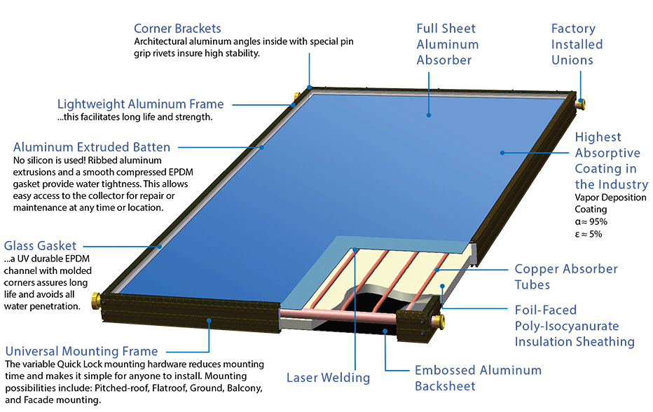
Solar Water Heater:
Solar water heaters are used to get 24 hrs hot water supply. Heat Collector is used to collecting heat from the sunlight. Puff insulated tank is then used to store the hot water. This tank has no partition between hot and cold water. Hot water stays on the top and cold water rests on the bottom. This is the reason every tank has a cold water intake point at the bottom side. Hot water outlet point and temperature meter connecting point at the top side. Depending upon the type of collector there are two types of water heater present.
ETC: In Evacuated Tube Collector specially made copper coated glass tubes were used to convert the sunlight into heat and the water gets heated up from there. Every tube has a three-layer coating with a vacuum between the glass to reduce the heat loss.
FPC: In Flat Plate Collector type system copper fins were used to convert the light into heat. The top side of the collector is made of tougfened glass to let the light in. The light falls on the couper fins that has a large surface area. These fins are specially coated with a mat black colour. As the light falls over the coper fins they gets heated up then this heat gets transferred to the water in the copper tube that is connected with the fins. Hot water goes towards the top and cold water takes its place from the bottom. Every collector has a lightweight aluminium body. The collector directly connected with the tank is called the primary collector. If required there is probation for an extra auxiliary collector. Standard collector size is 1m x 2m. Every collector is properly insulated from the back side to reduce heat loss.
Individual solar cell devices are often the electrical building blocks of photovoltaic modules, known colloquially as "solar panels". A PV module consists of several interconnected solar cells encapsulated into a single, long-lasting, stable unit. The key purpose of encapsulating a set of electrically connected solar cells is to protect them and their interconnecting wires from the typically harsh environment in which they are used. For example, solar cells, since they are relatively thin, are prone to mechanical damage (break) unless protected. In addition, the metal grid on the top surface of the solar cell and the wires interconnecting the individual solar cells may be corroded by water or water vapour. The two key functions of encapsulation are to prevent mechanical damage to the solar cells and to prevent water or water vapour from corroding the electrical contacts.
Many different types of PV modules exist and the module structure is often different for different types of solar cells or for different applications. For example, amorphous silicon solar cells are often encapsulated into a flexible array, while bulk silicon solar cells for remote power applications are usually rigid with glass front surfaces.
A Solar Panel has multiple layers from top to bottom they are -
Front Glass: The front glass protects the Solar Cells from the weather and impact from hail or dust. The glass is typically low Iron high-strength tempered glass which is 3.0 to 4.0mm thick and is designed to resist mechanical loads and extreme temperature changes. The IEC minimum standard impact test requires solar panels to withstand an impact of hail stones of 1 inch (25 mm) diameter travelling up to 60 mph (27 m/s). In the event of an impact tempered glass is also much safer than standard glass as it shatters into tiny fragments rather than sharp jagged sections.
Upper EVA Layer: EVA stands for ‘ethylene vinyl acetate’ which is a specially designed polymer highly transparent (plastic) layer used to encapsulate the cells and hold them in position during manufacture. It is extremely durable and tolerant of extreme temperatures and humidity, it plays an important part in long-term performance by preventing moisture and dirt ingress. EVA comes in thin sheets. Two layrs of EVA are used to make a sandwitch like arrangement where the cell assembly stays in middle. This sandwich is then heated to 150 °C to polymerize the EVA and bond the module together.
Solar Cell: Solar Cell is mainly the optoelectronic device that converts the light to electricity.
Lower EVA Layer: The lamination on either side of the PV cells provides some shock absorption and helps protect the cells and interconnecting wires from vibrations and sudden impact from hail stones and other objects. During manufacture the cells are first encapsulated with the EVA before being assembled within the glass and back sheet.
Backsheet: The backsheet is the rearmost layer of standard solar panels which acts as a moisture barrier and final external skin to provide both mechanical protection and electrical insulation. The backsheet material is made of various polymers or plastics including PP, PET and PVF which offer different levels of protection, thermal stability and long-term UV resistance. Nowadays Tedlar is uded as backsheet material. The backsheet layer is typically white in colour but is also available as clear or black, depending on the manufacturer and module.
The most common modules have 36 cells, 60 cells or 72 cells with bypass diodes. A 36-cell produces a maximum open circuit voltage of 17-18 Volts while a 60-cell module produces around 36-38 Volts. A 72-cell panel produces 46-47 Volts. With the Wp (Watt-Peak) of the module increase number of cells increases. Example 10 Wp, 20 Wp, and 40 Wp module comes with 36 cells in series. On the other hand, 325 Wp, 330 Wp, and 335 Wp modules come with 72 cells in series.
Module lifetimes and warranties on bulk silicon PV modules are over 20 years, indicating the robustness of an encapsulated PV module.
Every module comes with some technical specifications written on its back, and also in the Test Report. The main electrical specifications are:
Peak Power Pmax (Wp): The maximum power that can be drawn from a solar panel while tested with some standards. The Standard Test Condition (STC) is 1000 W/m2 irradiance, 25°C cell temperature, and AM1.5g spectrum.
Maximum Voltage Vmpp (V): This is the voltage available when the panel is connected to a load and is operating at its maximum capacity under standard test conditions.
Maximum Current Impp (A): This current is obtained when the solar panels are producing their maximum power under standard test conditions.
Open Circuit Voltage Voc (V): It is the maximum voltage a solar panel can produce under Standard Test Conditions without any load connected.
Short Circuit Current Isc (A): This is the highest current the solar panel cell can deliver without any damage at Full Load condition or Short Circuit Condition while it is in Standard Test Conditions.
Module Efficiency (%): It is defined as the ratio of energy produced by a solar cell to the energy it receives from the sun. The efficiency of solar panels depends on the efficiency of the solar cell. Most solar cells available in the market offer an efficiency of 17-19% and the highest efficiency of a commercial solar panel is about 23%.
The mechanical specifications are: Length × Width × Height