Wind energy is the kinetic energy associated with the movement of large masses of air. These motions result from uneven heating of the atmosphere by the sun, creating temperature, density and pressure differences. It is estimated that 1% of all solar radiation falling on the face of the earth is converted into kinetic energy of the atmosphere, 30% of which occurs in the lowest 1000 m of elevation. So it is thus an indirect form of solar energy.
Wind energy is harnessed as mechanical energy with the help of a wind turbine. This mechanical energy can be used in farm appliances, water pumping etc. It can also be converted to electric power and used locally or fed to a grid. A generator coupled to a wind turbine is known as an aero generator. Wind turbines are classified into two general types, Horizontal axis and Vertical axis.
Horizontal axis Wind Turbine: A horizontal axis machine has its blades rotating on an axis parallel to the ground. Depending upon the direction there are two types of wind turbine design. Upwind turbines are designed in such a way that they face into the wind. A tail vane is required to keep the blades facing toward the wind. While Downwind turbines face away from the wind so that the wind passes the tower before striking the blades. Some very large wind turbines use a motor-driven mechanism that turns the machine in response to a wind direction sensor mounted on the tower.
Vertical axis Wind Turbine: A vertical axis machine has its blades rotating on an axis perpendicular to the ground. A vertical axis machine need not be oriented to wind direction. It can utilise wind coming from any direction. Because the shaft is vertical, the transmission and generator can be mounted at ground level allowing easier servicing and a lighter-weight, lower-cost tower.
However, compared with the horizontal axis type, very few vertical axis machines are available commercially. A vertical wind turbine has multiple parts.
Blades: Wind turbines use blades to collect the wind’s kinetic energy. Turbines commonly have either two or three blades mounted on a rotor that sits horizontally to the ground. Wind flows over the blades creating lift (similar to the effect on airplane wings), which causes the blades to turn. A turbine does not necessarily have to have three blades; it can have two, four, or another number of blades. But the three-blade rotor has the best efficiency and other advantages.
Blades are not solid; they are hollow and are made of composite material to be light and strong. The trend is to make them larger (for more power), lighter, and stronger. The blades have the form of an airfoil (the same as the wings of an aeroplane) to be aerodynamic. As well, they are not flat and have a twist between their root and their tip.
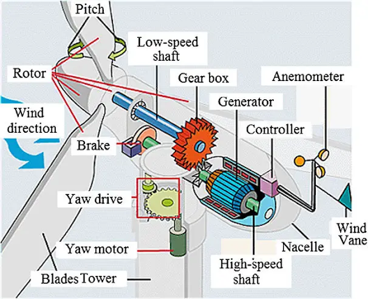
Pitch Drive: The blades can rotate up to 90° about their axes. This motion is called blade pitch. A pitch system turns blades out of the wind to control rotor speed and to keep the rotor from turning in winds that are too low or too high to produce electricity.
Rotor: The rotor is the rotating part of a turbine; it consists of (mostly) three blades and the central part that the blades are attached to.
Hub: The central part that the blades are attached to is called the hub. The function of the hub is to hold the blades and make it possible for them to rotate with the rest of the turbine.
Nacelle: The nacelle is housing on top of the tower that accommodates all the components that need to be on a turbine top. There are several components for the proper and healthy operation of a complicated electromechanical system turbine. A major turbine part among these components is the generator and the turbine shaft that transfers the harvested power from wind to the generator through a gearbox.
Generator: The generator is the component that converts the mechanical energy of the rotor, harnessed from wind to electrical energy. A generator has the same structure as an electric motor. At the commercial production level, all electricity generation is in the three-phase alternative current. The generator associated with wind turbines is the induction generator because a synchronous generator must turn at a tightly controlled constant speed (to maintain a constant frequency). A generator must be rotated at a speed corresponding to the frequency of the electric network, it must be rotated faster than the turbine rotor. Most generators need to be turned at 1500 rpm (for 50 Hz) and 1800 rpm (for 60 Hz). In no way, it is feasible for a turbine rotor to move that fast. A gearbox increases the turbine rotor (main shaft) rotational speed to a speed that can be used by the generator.
Shaft and Gearbox: The gearbox is a vital component of wind turbines; it resides in the nacelle. A gearbox increases the main shaft speed from around 12–25 rpm* (for most of today’s turbines) to a speed suitable for its generator. For this reason, the shaft on the generator side is called a “high-speed shaft” and the Shaft on the blade side is called a “low-speed shaft”.
Yaw Drive: Because a turbine must follow the wind and adjust its orientation to the wind direction, its rotor needs to rotate with respect to the tower. This rotation is called yaw motion in which the nacelle and the rotor revolve about the tower axis.
Tower: The wind turbine tower is often made from steel or concrete. Generally, taller towers enable turbines to capture more kinetic wind energy because wind speed increases with height.
Anemometer: An anemometer measures the wind speed and transmits wind speed data to the controller. The controller starts the wind turbine at speeds of about 12 to 25 km/h. The controller shuts off the wind turbine at about 90 km/h to protect the turbines from damaging winds. Brakes (which can be mechanical, electrical or hydraulic) can be used to stop the rotor in emergencies.
Wind Vane: A wind vane measures the wind direction and communicates with the yaw drive to orient the turbine properly with respect to the wind. A yaw drive, powered by a yaw motor, orients upwind turbines to keep them facing the wind when the direction changes. A yaw drive is not needed in downwind turbines as the wind automatically blows the rotor away from it.
Working Principle: The blades turn a low-speed shaft at about 30-60 rotations per minute (rpm). A gearbox connects the low-speed shaft to the high-speed shaft and increases the rotational speeds from about 30-60 rpm to about 1,000-1,800 rpm. 1,000-1,800 rpm is the rotational speed required by most generators to produce electricity. The high-speed shaft drives the generator which produces AC electrical current. Slip-ring-type asynchronous generators are used for power generation.
The electric current produced by the generator flows through a cable running down through the inside of the turbine tower. If the electricity is flowing to the grid, it's converted to an even higher voltage (130,000 volts or more) by a substation nearby, which services many turbines.
Reference:
- https://www.suzlon.com/in-en/energy-solutions/s120-wind-turbine-generator


.jpg)


