Before we controlled the Led Widget of the Blynk app. Now we will learn about the Button Widget and see how to change the circuit diagram so that we could control large electrical loads. This is a basic Home Automation Project.
For this project we need
- NodeMCU
- Blynk App Installed in a Android Phone
- Relay Board
- LED as Load
Please follow the Step by Step Blynk Installation Guide to install the Blynk app on your phone. Then add the Button Widget and LED Widget (optional). Then tap on the Button Widget and make V2 as the output as in the image below.
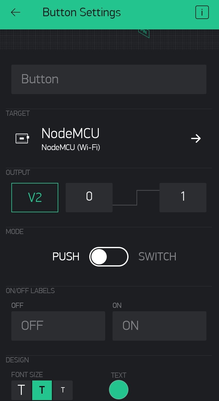
Then tap on the LED Widget and change V1 as the Input.

Then connect your node MCU to your desktop or laptop. If you are using NodeMCU for the first time then you have to add Node MCU to your Arduino IDE. Please follow the step-by-step tutorial for Programming NodeMCU Step by Step Using Arduino IDE.
Now open the IDE copy-paste the code. Carefully delete YourAuthToken and paste your auth code there. Then delete YourNetworkName and write your WiFi router or phone's hotspot name there. Finally, delete YourPassword and put your Wi-Fi or hotspot password. Then you can upload the code. Once uploaded your NodeMCU should get connected to your WiFi network.
Now if you tap on the Play at the top right corner the icon would turn to Stop
 and you will be able to see your device online.
Now use the Button on the Blynk app to control the LED on NodeMCU.
The LED on the NodeMCU is connected to the GPIO2 or D4 pin of your NodeMCU. So if you connect a relay board at GPIO2 you will be able to control the relay also. The operation of the relay board will be discussed later on another blog.
Source Code: