February 13, 2021

IoT Using Blynk - Controlling Load using Push Button Widget

Before we controlled the Led Widget of the Blynk app. Now we will learn about the Button Widget and see how to change the circuit diagram so that we could control large electrical loads. This is a basic Home Automation Project.

For this project we need 

  • NodeMCU 

  •  Blynk App Installed in a Android Phone 

  •  Relay Board

  •  LED as Load

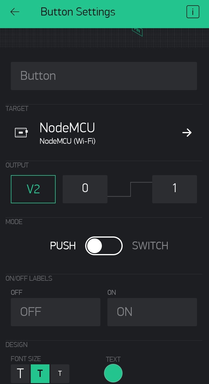
Please follow the Step by Step Blynk Installation Guide to install the Blynk app on your phone. Then add the Button Widget and LED Widget (optional). Then tap on the Button Widget and make V2 as the output as in the image below. 

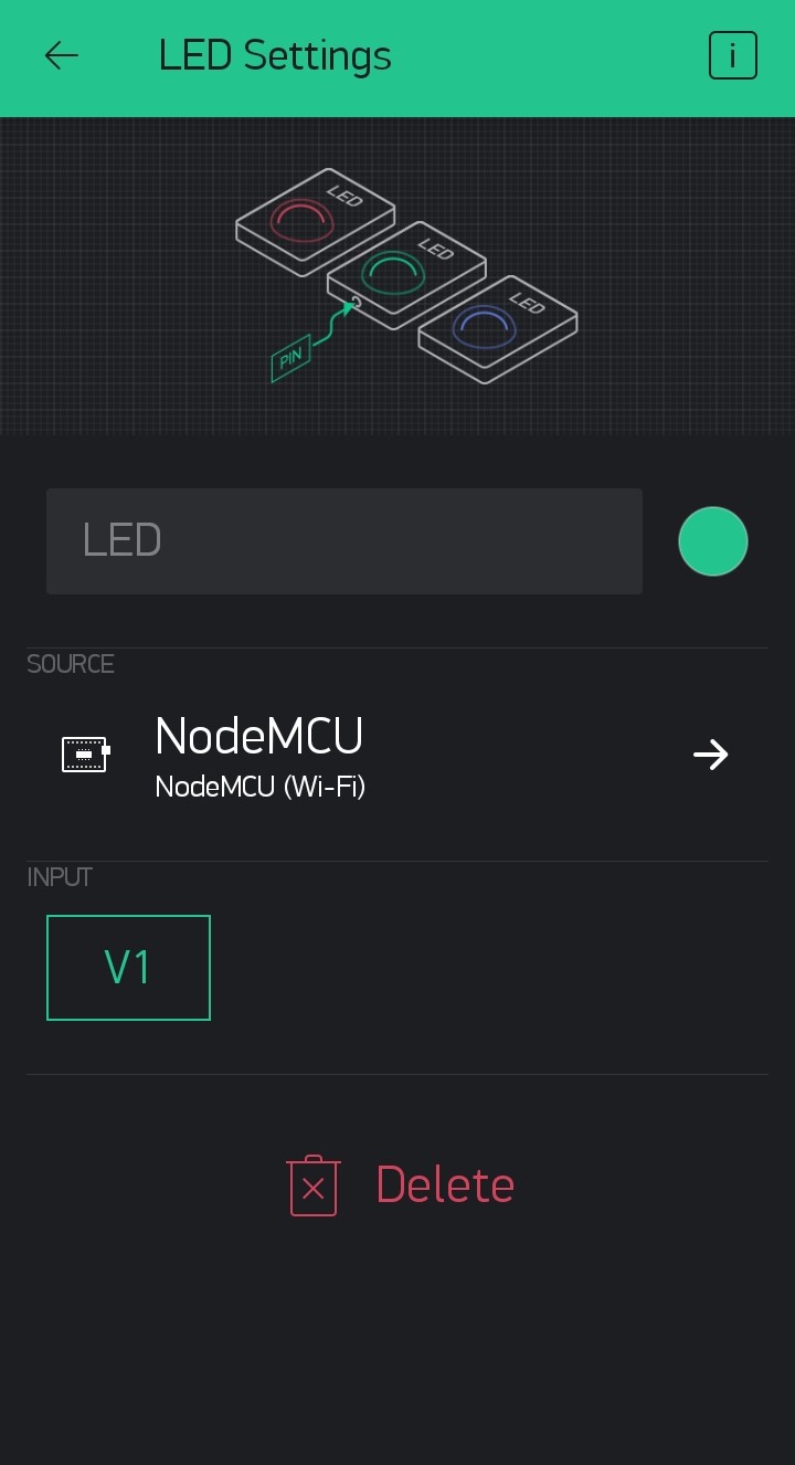
Then tap on the LED Widget and change V1 as the Input.


Then connect your node MCU to your desktop or laptop. If you are using NodeMCU for the first time then you have to add Node MCU to your Arduino IDE. Please follow the step-by-step tutorial for Programming NodeMCU Step by Step Using Arduino IDE.

Now open the IDE copy-paste the code. Carefully delete YourAuthToken and paste your auth code there. Then delete YourNetworkName and write your WiFi router or phone's hotspot name there. Finally, delete YourPassword and put your Wi-Fi or hotspot password. Then you can upload the code. Once uploaded your NodeMCU should get connected to your WiFi network.

Now if you tap on the Play at the top right corner the icon would turn to Stopand you will be able to see your device online.

Now use the Button on the Blynk app to control the LED on NodeMCU. 

The LED on the NodeMCU is connected to the GPIO2 or D4 pin of your NodeMCU. So if you connect a relay board at GPIO2 you will be able to control the relay also. The operation of the relay board will be discussed later on another blog.

Source Code:

Video:

January 09, 2021

IoT Using Blynk - Blinking LED Widget

We already blinked the built-in LED of NodeMCU. We have also discussed the Blynk App, how to install and set it up. Now we will go for the Led of Blynk app. These Widgets act as virtual hardware. Our Aim is to blink the Virtual LED with the actual LED in NodeMCU.

If you are new then follow the Step by Step Blynk Installation Guide to install the Blynk app on your phone. If you are using NodeMCU for the first time then you have to add NodeMCU to your Arduino IDE. Please follow the step-by-step tutorial for Programming NodeMCU Step by Step Using Arduino IDE.

In our last blog, we got a mail from Blynk which has Auth Token. This Auth Token is a unique identifier that is particularly dedicated to a controller or hardwire. Think of it as your identity number of the NodeMCU. With this ID number, Blynk identifies your controller and differentiates it from all other controllers that are running by others all around the globe.

For this project, we will only need 

  • NodeMCU 

  •  Blynk App Installed in a Android Phone 

Step 1: Open Arduino IDE.


Step 2: Copy-Paste the code there.


Step 3: Copy the Auth-Code that is sent to your mail-id. Just delete YourAuthToken and paste your auth code there. Then delete YourNetworkName and write your WiFi router or phones hotspot name there. Finally, delete YourPassword and put your Wi-Fi or hotspot password.

Step 4: Click on Tools and make sure that you have selected the right device and the right port. For me its NodeMCU and COM11. (For you it may not be COM11 so check before uploading)

Step 5: Finally, save the code and hit the upload button. 

Then go to the settings of the LED Widget. You can do it by tapping on the LED widget. Set V1 as the Input.


Video: IoT Using NodeMCU and Blynk

Source Code:


January 08, 2021

Blynk

Blynk is a free IoT platform. Let's set up Blynk step by step.

Step 1: Open play store, search for the app Blynk and install the app.


Step 2: Install the app in your device.

Step 3: Find the app icon looks like the one shown below. Then open it.

Step 4: If you have an account log in otherwise click on Create New Account. You can log in using your Facebook account also.

Step 5: Enter your email id and then create a password and enter it. Note that this is not your email id's password. You have to create a different password.

Step 6: Click Sign Up

Step 7: Read the note and Click on Cool! Got it. This service is not totally free but partially free. We will discuss it later.

Step 8: Now its time to make a new project. Click on New Project.

Step 9: Click Project Name to edit it and give it a new name.

Step 10: In my case, I've chosen Test Project.

Step 11: Then Click the drop-down menu and find the controller you are using and select OK. In my case, I have chosen NodeMCU because in my last blog was about programming NodeMCU.

Step 12: Select Connection Type as Wi-Fi and click Create.

Step 13: Click ok and find the Auth token from your email id. We will discuss this Auth Token and how to use it in our next blog. 


Step 14: This is a blank project. Now you have to add some widgets. Now, these widgets are not free. You get only 2000 Units of energy and this energy you have spent to get a widget. The declaration in Step 7 was about this.

Step 15: There are various types of widgets and all have prise. So choose your weapon wisely.

I'll discuss some of these widgets later in another blog.


December 17, 2020

Programming NodeMCU Step by Step Using Arduino IDE

Programming NodeMCU is as easy as programming as Arduino UNO. You just have to equip your Arduino IDE.

First Connect the NodeMCU to your PC or Laptop using a micro USB data cable.

Then go to the link (NodeMCU Driver) to download the driver. Download and Extract the driver and install it.

Now open the Arduino IDE and go to File > Preferences 

In the Preferences window, you will find Additional Boards Manager URLs. Just copy the line below and paste it there.

http://arduino.esp8266.com/stable/package_esp8266com_index.json


Then close the IDE and reopen it.

Now go to Tools > Board: > Boards Manager


Open the Boards Manager and search for nodemcu.


Then install the most updated version from there.

That's all you have to do. Now let's check what changes have come.


Now lets program nodeMCU with a basic example program Blink. 
Go to File > Examples > Basic > Blink

Now Go to Tools > Boards: and select NodeMCU


After selecting the board go to Port and select the right communication port. Hit the Upload button.


The upload may take a few seconds and after that, you will find a screen like this stating that uploading is done. During the upload the led near pin D0 might blink several times but after the uploading is complete the led will keep glowing for 1 sec and staying off for 1 second.


Video: Coming Soon

NodeMCU Driver Link: https://github.com/nodemcu/nodemcu-devkit/tree/master/Drivers

Introduction to Node MCU

 NodeMCU is an open-source IoT platform. It includes firmware that runs on the ESP8266 Wi-Fi system on a chip(SoC) from Espressif Systems and hardware which is based on the ESP-12 module. The term "NodeMCU" by default refers to the firmware rather than the development kits. The firmware uses the Lua scripting language. It is based on the eLua project and built on the Espressif Non-OS SDK for ESP8266.

In simple words, NodeMCU is a WiFi-enabled microcontroller. It has a micro USB connector so it could be connected to any computer using data cable. The only thing that you must remember that it is a 3.3V logic level device. It means you will get a 3.3V digital high signal and giving more than 3.3V signal is not safe for the controller, however, the input voltage can vary from 5 to 12V.

NodeMCU Pinout contains 9 Digital pins, 1 Analog Pins, 1 Reset Pins & 4 Power Pins. Although some pins are very difficult to use sometimes. 

Let's have a look at the pinout.
 

  • D0 - D8 are Digital Pins
  • A0 is the only analog pin
The Micro USB port makes it very easy to connect with PC. Node MCU can be programmed using Arduino IDE but when we program it with Arduino IDE the original Lua firmware gets overwritten or in other words lost.
a
In our next blog, we will discuss the programming process of the NodeMCU.

September 06, 2020

Solar Energy Trainer Kit

Effect of Series
Effect of Parallal
IV Curve 
Video

Solar Pumping Systems

    Pumps are devices that use energy to raise, transport, or compress fluids. Pumps are divided into two main categories, Positive Displacement Pumps and Dynamic Pumps. They also have many types.

  1. Positive Displacement Pump: Pumps in which displacement is accomplished mechanically are called positive displacement pumps. There are many types of Displacement Pumps.
    a. Diaphragm pumps
    b. Gear pumps
    c. Peristaltic pumps
    d. Cam pumps
    e. Piston pumps
  2. Dynamic Pump: Kinetic pumps impart kinetic energy to the fluid using a rapidly rotating impeller. There are many types of Dynamic Pumps.
    a. Centrifugal pumps
    b. Vertical Pumps

    All these types of pumps have their specific pumping fluid nature (i.e. viscosity, density), fluid pressure, and flow rate. Hence their application is also different.

    Depending upon the installation locations pumps are of two types, pumps that are installed on the surface and pumps that are submerged under fluid.

  1. Surface Pumps: Surface water pumps A surface water pump helps in pumping out water from a water body, like a well, or a river, and transports it to different destinations.


  1. Submersible Pumps: A submersible pump, also known as an electrical submersible pump, is a water pump that is completely submerged in the water and can be used for a variety of applications. The electric motor used in the process is hermetically sealed and also close-coupled to the pump. One of the major advantages of a submersible pump is that it does not require priming because it has already been submerged in the liquid.


    Solar Pumping Systems are nowadays very common. SPV modules are used to run pumps to get water. Depending on  These systems come in two types. one with Submersible pumps and one with surface pumps. 

    Most of the time pumps run with AC power. On the other hand, SPV modules provide us with DC. To integrate them together one VFD-based pump controller is used. Sometimes these controller comes with AC power input terminals, and they can be run using AC Power at night also. They also can be equipped with a float switch so that the pump can be turned on and off depending on the water level of the reserver, tank or borewell.

    Variable Frequency Drive: A variable-frequency drive (VFD) is a type of motor drive used in electro-mechanical drive systems to control AC motor speed and torque by varying motor input frequency and, depending on the topology, to control associated voltage or current variation.

There are mainly two types of applications for solar pumping systems.

Solar Pumping for Irrigation where is taken from a borewell by a submersible pump or from a river, lake or pond-like waterbody by a surface pump and used for irrigation.


Solar Pumping System for Drinking Water Project. Where a submersible pump is used to pump groundwater and store it in a tank. Then after filtering the water, it can be used locally. Or using a surface pump it can be pumped to water distribution networks.


Reference:

  1. https://en.wikipedia.org/wiki/Pump
  2. https://www.britannica.com/technology/pump
  3. https://www.haoshpump.com/different-types-of-pumps/
  4. https://multiphase-corp.com/articles/types-of-pumps-and-their-working-principles/
  5. https://www.cgglobal.com/our_business/Industrial/Drives-and-Automation/Industrial-Drives/Emotron-VSR-Solar-Drive
  6. https://www.crompton.co.in/blogs/pumps/what-is-a-submersible-pump-understanding-its-working-and-applications
  7. https://www.crigroups.com/pump/surface-water-pumps/