We already blinked the built-in LED of NodeMCU. We have also discussed the Blynk App, how to install and set it up. Now we will go for the Led of Blynk app. These Widgets act as virtual hardware. Our Aim is to blink the Virtual LED with the actual LED in NodeMCU.
In our last blog, we got a mail from Blynk which has Auth Token. This Auth Token is a unique identifier that is particularly dedicated to a controller or hardwire. Think of it as your identity number of the NodeMCU. With this ID number, Blynk identifies your controller and differentiates it from all other controllers that are running by others all around the globe.
For this project, we will only need
NodeMCU
Blynk App Installed in a Android Phone
Step 1: Open Arduino IDE.
Step 2: Copy-Paste the code there.
Step 3: Copy the Auth-Code that is sent to your mail-id. Just delete YourAuthToken and paste your auth code there. Then delete YourNetworkNameand write your WiFi router or phones hotspot name there. Finally, delete YourPassword and put your Wi-Fi or hotspot password.
Step 4: Click on Tools and make sure that you have selected the right device and the right port. For me its NodeMCU and COM11. (For you it may not be COM11 so check before uploading)
Step 5: Finally, save the code and hit the upload button.
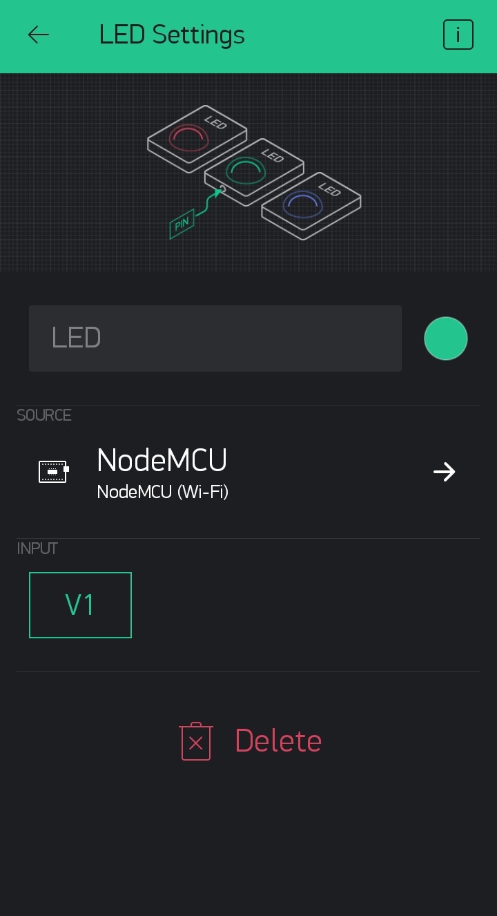
Then go to the settings of the LED Widget. You can do it by tapping on the LED widget. Set V1 as the Input.
Blynk is a free IoT platform. Let's set up Blynk step by step.
Step 1: Open play store, search for the app Blynk and install the app.
Step 2: Install the app in your device.
Step 3: Find the app icon looks like the one shown below. Then open it.
Step 4: If you have an account log in otherwise click on Create New Account. You can log in using your Facebook account also.
Step 5: Enter your email id and then create a password and enter it. Note that this is not your email id's password. You have to create a different password.
Step 6: Click Sign Up
Step 7: Read the note and Click on Cool! Got it. This service is not totally free but partially free. We will discuss it later.
Step 8: Now its time to make a new project. Click on New Project.
Step 9: Click Project Name to edit it and give it a new name.
Step 10: In my case, I've chosen Test Project.
Step 11: Then Click the drop-down menu and find the controller you are using and select OK. In my case, I have chosen NodeMCU because in my last blog was about programming NodeMCU.
Step 12: Select Connection Type as Wi-Fi and click Create.
Step 13: Click ok and find the Auth token from your email id. We will discuss this Auth Token and how to use it in our next blog.
Step 14: This is a blank project. Now you have to add some widgets. Now, these widgets are not free. You get only 2000 Units of energy and this energy you have spent to get a widget. The declaration in Step 7 was about this.
Step 15: There are various types of widgets and all have prise. So choose your weapon wisely.
I'll discuss some of these widgets later in another blog.
That's all you have to do. Now let's check what changes have come.
Now lets program nodeMCU with a basic example program Blink. Go to File > Examples > Basic > Blink
Now Go to Tools > Boards: and select NodeMCU
After selecting the board go to Port and select the right communication port. Hit the Upload button.
The upload may take a few seconds and after that, you will find a screen like this stating that uploading is done. During the upload the led near pin D0 might blink several times but after the uploading is complete the led will keep glowing for 1 sec and staying off for 1 second.
NodeMCU is an open-source IoT platform. It includes firmware that runs on the ESP8266 Wi-Fi system on a chip(SoC) from Espressif Systems and hardware which is based on the ESP-12 module. The term "NodeMCU" by default refers to the firmware rather than the development kits. The firmware uses the Lua scripting language. It is based on the eLua project and built on the Espressif Non-OS SDK for ESP8266.
In simple words, NodeMCU is a WiFi-enabled microcontroller. It has a micro USB connector so it could be connected to any computer using data cable. The only thing that you must remember that it is a 3.3V logic level device. It means you will get a 3.3V digital high signal and giving more than 3.3V signal is not safe for the controller, however, the input voltage can vary from 5 to 12V.
NodeMCU Pinout contains 9 Digital pins, 1 Analog Pins, 1 Reset Pins & 4 Power Pins. Although some pins are very difficult to use sometimes. Let's have a look at the pinout.
D0 - D8 are Digital Pins
A0 is the only analog pin
The Micro USB port makes it very easy to connect with PC. Node MCU can be programmed using Arduino IDE but when we program it with Arduino IDE the original Lua firmware gets overwritten or in other words lost.
a
In our next blog, we will discuss the programming process of the NodeMCU.
Pumps are devices that use energy to raise, transport, or compress fluids. Pumps are divided into two main categories, Positive Displacement Pumps and Dynamic Pumps. They also have many types.
Positive Displacement Pump: Pumps in which displacement is accomplished mechanically are called positive displacement pumps. There are many types of Displacement Pumps. a. Diaphragm pumps b. Gear pumps c. Peristaltic pumps d. Cam pumps e. Piston pumps
Dynamic Pump: Kinetic pumps impart kinetic energy to the fluid using a rapidly rotating impeller. There are many types of Dynamic Pumps. a. Centrifugal pumps b. Vertical Pumps
All these types of pumps have their specific pumping fluid nature (i.e. viscosity, density), fluid pressure, and flow rate. Hence their application is also different.
Depending upon the installation locations pumps are of two types, pumps that are installed on the surface and pumps that are submerged under fluid.
Surface Pumps: Surface water pumps A surface water pump helps in pumping out water from a water body, like a well, or a river, and transports it to different destinations.
Submersible Pumps: A submersible pump, also known as an electrical submersible pump, is a water pump that is completely submerged in the water and can be used for a variety of applications. The electric motor used in the process is hermetically sealed and also close-coupled to the pump. One of the major advantages of a submersible pump is that it does not require priming because it has already been submerged in the liquid.
Solar Pumping Systems are nowadays very common. SPV modules are used to run pumps to get water. Depending on These systems come in two types. one with Submersible pumps and one with surface pumps.
Most of the time pumps run with AC power. On the other hand, SPV modules provide us with DC. To integrate them together one VFD-based pump controller is used. Sometimes these controller comes with AC power input terminals, and they can be run using AC Power at night also. They also can be equipped with a float switch so that the pump can be turned on and off depending on the water level of the reserver, tank or borewell.
Variable Frequency Drive: A variable-frequency drive (VFD) is a type of motor drive used in electro-mechanical drive systems to control AC motor speed and torque by varying motor input frequency and, depending on the topology, to control associated voltage or current variation.
There are mainly two types of applications for solar pumping systems.
Solar Pumping for Irrigation where is taken from a borewell by a submersible pump or from a river, lake or pond-like waterbody by a surface pump and used for irrigation.
Solar Pumping System for Drinking Water Project. Where a submersible pump is used to pump groundwater and store it in a tank. Then after filtering the water, it can be used locally. Or using a surface pump it can be pumped to water distribution networks.
Protective Relays: In electrical engineering, a protective relay is a relay device designed to trip a circuit breaker when a fault is detected. The first protective relays were electromagnetic devices, relying on coils operating on moving parts to provide detection of abnormal operating conditions such as over-current, overvoltage, reverse power flow, over-frequency, and under-frequency. Microprocessor-based digital protection relays now emulate the original devices, as well as providing types of protection and supervision impractical with electromechanical relays. Electromechanical relays provide only a rudimentary indication of the location and origin of a fault. In many cases, a single microprocessor relay provides functions that would take two or more electromechanical devices. By combining several functions in one case, numerical relays also save capital cost and maintenance cost over electromechanical relays.
Types according to construction
1. Electromechanical Relay: Electromechanical relays can be classified into several different types as follows: a. Attracted Armature b. Moving Coil c. Induction d. Motor Operated e. Mechanical f. Thermal
2. Induction disc overcurrent Relay: Magnetic system in induction disc overcurrent relays is designed to detect over-currents in a power system and operate with a pre-determined time delay when certain overcurrent limits have been reached. In order to operate, the magnetic system in the relays produces a torque that acts on a metal disc to make contact. "Induction" disk meters work by inducing currents in a disk that is free to rotate; the rotary motion of the disk operates a contact. Induction relays require alternating current; if two or more coils are used, they must be at the same frequency otherwise no net operating force is produced. These electromagnetic relays use the induction principle discovered by Galileo Ferraris in the late 19th century.
3. Static Relay: The application of electronic amplifiers to protective relays was described as early as 1928, using vacuum tube amplifiers, and continued up to 1956. Devices using electron tubes were studied but never applied as commercial products, because of the limitations of vacuum tube amplifiers. A relatively large standby current is required to maintain the tube filament temperature; inconvenient high voltages are required for the circuits, and vacuum tube amplifiers had difficulty with incorrect operation due to noise disturbances. Static relays have no or few moving parts and became practical with the introduction of the transistor. Measuring elements of static relays have been successfully and economically built up from diodes, Zener diodes, avalanche diodes, unijunction transistors, p-n-p, and n-p-n bipolar transistors, field-effect transistors, or their combinations. Static relays offer the advantage of higher sensitivity than purely electromechanical relays because the power to operate output contacts is derived from a separate supply, not from the signal circuits. Static relays eliminated or reduced contact bounce, and could provide fast operation, long life, and low maintenance.
4. Digital Relay: Digital protective relays were in their infancy during the late 1960s. An experimental digital protection system was tested in the lab and in the field in the early 1970s. Unlike the relays mentioned above, digital protective relays have two main parts: hardware and software. The world's first commercially available digital protective relay was introduced to the power industry in 1984 by Schweitzer Engineering Laboratories (SEL) based in Pullman, Washington. In spite of the developments of complex algorithms for implementing protection functions, the microprocessor-based-relays marketed in the 1980s did not incorporate them. A microprocessor-based digital protection relay can replace the functions of many discrete electromechanical instruments. These relays convert voltage and currents to digital form and process the resulting measurements using a microprocessor. The digital relay can emulate functions of many discrete electromechanical relays in one device, simplifying protection design and maintenance. Each digital relay can run self-test routines to confirm its readiness and alarm if a fault is detected. Digital relays can also provide functions such as communications (SCADA) interface, monitoring of contact inputs, metering, waveform analysis, and other useful features. Digital relays can, for example, store multiple sets of protection parameters, which allows the behavior of the relay to be changed during the maintenance of attached equipment. Digital relays also can provide protection strategies impossible to implement with electromechanical relays. This is particularly so in long-distance high voltage or multi-terminal circuits or in lines that are series or shunt compensated. They also offer benefits in self-testing and communication to supervisory control systems.
5. Numerical Relay: The distinction between digital and numerical protection relay rests on points of fine technical detail, and is rarely found in areas other than Protection. Numerical relays are the product of the advances in technology from digital relays. Generally, there are several different types of numerical protection relays. Each type, however, shares a similar architecture, thus enabling designers to build an entire system solution that is based on a relatively small number of flexible components. They use high-speed processors executing appropriate algorithms. Most numerical relays are also multifunctional and have multiple setting groups each often with tens or hundreds of settings.