October 18, 2024

ADXL345 Accelerometer Interface With Arduino


The ADXL345 is a small, thin, low-power, 3-axis accelerometer with high resolution (13-bit) measurement at up to ±16g [1, 2].


Components Required:
  • ADXL345 Accelerometer 
  • Arduino
  • Jumper Wires
  • Power Supply / Data Cable

Connection Diagram:

Before you upload the code library needs to be installed. Please follow the below-mentioned instructions to install the library.

https://creativestudio1973.blogspot.com/2019/11/introduction-to-arduino-library-manager.html

Source Code:


 Video:

Reference:
[1] https://www.analog.com/en/products/adxl345.html#part-details
[2] https://www.analog.com/media/en/technical-documentation/data-sheets/adxl345.pdf

May 28, 2024

Solar Wind Hybrid System

 In a solar-wind hybrid system, Solar and Wind energy are used together to generate power. This power can be supplied to the load and used to charge the battery so that the energy can be used later.

To learn more about Solar follow the links below:
Solar Panel: https://creativestudio1973.blogspot.com/2021/06/introduction-to-solar-panel.html
Solar Off-Grid System: https://creativestudio1973.blogspot.com/2020/09/off-grid-systems.html

To learn more about Batteries follow the link below:
https://creativestudio1973.blogspot.com/2020/09/battery.html

To learn more about Wind Energy follow the link below:
https://creativestudio1973.blogspot.com/2024/05/wind-turbine.html

Video:

Wind Turbine

Wind energy is the kinetic energy associated with the movement of large masses of air. These motions result from uneven heating of the atmosphere by the sun, creating temperature, density and pressure differences. It is estimated that 1% of all solar radiation falling on the face of the earth is converted into kinetic energy of the atmosphere, 30% of which occurs in the lowest 1000 m of elevation. So it is thus an indirect form of solar energy.

    Wind energy is harnessed as mechanical energy with the help of a wind turbine. This mechanical energy can be used in farm appliances, water pumping etc. It can also be converted to electric power and used locally or fed to a grid. A generator coupled to a wind turbine is known as an aero generator. Wind turbines are classified into two general types, Horizontal axis and Vertical axis.

Horizontal axis Wind Turbine: A horizontal axis machine has its blades rotating on an axis parallel to the ground. Depending upon the direction there are two types of wind turbine design. Upwind turbines are designed in such a way that they face into the wind. A tail vane is required to keep the blades facing toward the wind. While Downwind turbines face away from the wind so that the wind passes the tower before striking the blades. Some very large wind turbines use a motor-driven mechanism that turns the machine in response to a wind direction sensor mounted on the tower.


Vertical axis Wind Turbine: A vertical axis machine has its blades rotating on an axis perpendicular to the ground. A vertical axis machine need not be oriented to wind direction. It can utilise wind coming from any direction. Because the shaft is vertical, the transmission and generator can be mounted at ground level allowing easier servicing and a lighter-weight, lower-cost tower.


    However, compared with the horizontal axis type, very few vertical axis machines are available commercially. A vertical wind turbine has multiple parts.
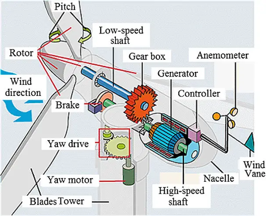
Blades: Wind turbines use blades to collect the wind’s kinetic energy. Turbines commonly have either two or three blades mounted on a rotor that sits horizontally to the ground. Wind flows over the blades creating lift (similar to the effect on airplane wings), which causes the blades to turn. A turbine does not necessarily have to have three blades; it can have two, four, or another number of blades. But the three-blade rotor has the best efficiency and other advantages.

    Blades are not solid; they are hollow and are made of composite material to be light and strong. The trend is to make them larger (for more power), lighter, and stronger. The blades have the form of an airfoil (the same as the wings of an aeroplane) to be aerodynamic. As well, they are not flat and have a twist between their root and their tip. 

Pitch Drive: The blades can rotate up to 90° about their axes. This motion is called blade pitch. A pitch system turns blades out of the wind to control rotor speed and to keep the rotor from turning in winds that are too low or too high to produce electricity.

Rotor: The rotor is the rotating part of a turbine; it consists of (mostly) three blades and the central part that the blades are attached to.

Hub: The central part that the blades are attached to is called the hub. The function of the hub is to hold the blades and make it possible for them to rotate with the rest of the turbine.

Nacelle: The nacelle is housing on top of the tower that accommodates all the components that need to be on a turbine top. There are several components for the proper and healthy operation of a complicated electromechanical system turbine. A major turbine part among these components is the generator and the turbine shaft that transfers the harvested power from wind to the generator through a gearbox.

Generator: The generator is the component that converts the mechanical energy of the rotor, harnessed from wind to electrical energy. A generator has the same structure as an electric motor. At the commercial production level, all electricity generation is in the three-phase alternative current. The generator associated with wind turbines is the induction generator because a synchronous generator must turn at a tightly controlled constant speed (to maintain a constant frequency). A generator must be rotated at a speed corresponding to the frequency of the electric network, it must be rotated faster than the turbine rotor. Most generators need to be turned at 1500 rpm (for 50 Hz) and 1800 rpm (for 60 Hz). In no way, it is feasible for a turbine rotor to move that fast. A gearbox increases the turbine rotor (main shaft) rotational speed to a speed that can be used by the generator.

Shaft and Gearbox: The gearbox is a vital component of wind turbines; it resides in the nacelle. A gearbox increases the main shaft speed from around 12–25 rpm* (for most of today’s turbines) to a speed suitable for its generator. For this reason, the shaft on the generator side is called a “high-speed shaft” and the Shaft on the blade side is called a “low-speed shaft”.

Yaw Drive: Because a turbine must follow the wind and adjust its orientation to the wind direction, its rotor needs to rotate with respect to the tower. This rotation is called yaw motion in which the nacelle and the rotor revolve about the tower axis.

Tower: The wind turbine tower is often made from steel or concrete. Generally, taller towers enable turbines to capture more kinetic wind energy because wind speed increases with height.

Anemometer: An anemometer measures the wind speed and transmits wind speed data to the controller. The controller starts the wind turbine at speeds of about 12 to 25 km/h. The controller shuts off the wind turbine at about 90 km/h to protect the turbines from damaging winds. Brakes (which can be mechanical, electrical or hydraulic) can be used to stop the rotor in emergencies.

Wind Vane: A wind vane measures the wind direction and communicates with the yaw drive to orient the turbine properly with respect to the wind. A yaw drive, powered by a yaw motor, orients upwind turbines to keep them facing the wind when the direction changes. A yaw drive is not needed in downwind turbines as the wind automatically blows the rotor away from it.

Working Principle: The blades turn a low-speed shaft at about 30-60 rotations per minute (rpm). A gearbox connects the low-speed shaft to the high-speed shaft and increases the rotational speeds from about 30-60 rpm to about 1,000-1,800 rpm. 1,000-1,800 rpm is the rotational speed required by most generators to produce electricity. The high-speed shaft drives the generator which produces AC electrical current. Slip-ring-type asynchronous generators are used for power generation. 

    The electric current produced by the generator flows through a cable running down through the inside of the turbine tower. If the electricity is flowing to the grid, it's converted to an even higher voltage (130,000 volts or more) by a substation nearby, which services many turbines.


Reference:
  1. https://www.suzlon.com/in-en/energy-solutions/s120-wind-turbine-generator


May 13, 2024

AC Motor Starter

 DOL Starter

Star-Delta Starter

AC Motor

SQIM
WRIM

DC Motor Starter

Starters are used to protect DC motors from damage that can be caused by very high current and torque during startup. They do this by providing external resistance to the motor, which is connected in series to the motor’s armature winding and restricts the current to an acceptable level. Then the removal of this resistance is done in steps as the motor accelerates.

It is very important and desirable to provide the starter with protective devices to enable the starter arm to return to the OFF position for the following conditions.

  1. when the supply fails, thus preventing the armature from being directly across the mains when this voltage is restored. For this purpose, we use a no-volt release coil.
  2. when the motor becomes overloaded or develops a fault causing the motor to take an excessive current. For this purpose, we use an overload-release coil.
Types of Starter
  1. Two-point starter
  2. Three-point starter
  3. Four-point starter
  • Three-point starter:

  1. In a three-point starter, the no-volt release coil is connected in series with the
  2. Shunt field circuit so that it carries the shunt field current.
  3. While exercising speed control through the field regulator, the field current may be weakened to such an extent that the no-volt release coil may not be able to keep the starter arm in the ON position.
  4. This may disconnect the motor from the supply when it is not desired. This drawback is overcome in the four-point starter.
  • Four-point starter:

  1.  In a four-point starter, the no-volt release coil is connected directly across the supply line through a protective resistance R.
  2. Now the no-volt release coil circuit is independent of the shunt field circuit. Therefore, proper speed control can be exercised without affecting the operation of the no-volt release coil
  3. Note that the only difference between a three-point starter and a four-point starter is the method in which a no-volt release coil is connected. However, the working of the two starters is the same.
  4. It may be noted that the three-point starter also provides protection against an open-field Circuit. This protection is not provided by the four-point starter.
 
 
  • Two-point starter:
  1. This starter is only for D.C. series motors. The basic construction of a two-point starter is similar to that of a three-point starter except for the fact that it has only two terminals namely line (L) and field (F).
  2. The F terminal is one end of the series combination of field and the armature winding. The action of the starter is similar to that of a three-phase starter.
  3. The main problem in the case of d.c. the series motor is its speeding action when the load is less.
  4. This can be prevented using two-point starters. The no-volt coil is connected in series with the motor so both currents are equal.
  5. In a no-load situation load current drawn by the motor decreases causing the no-volt coil losses its required magnetism and release the handle to the OFF position.
Reference:
[1] https://www.scribd.com/doc/38037500/d-c-Motor-Starter
[2] https://www.javatpoint.com/starting-of-dc-motors

DC Motor

A DC motor, or direct current motor, is an electrical motor that uses AC current to transform electrical energy into mechanical energy. There are two types of DC motors based on the construction such as 

  1. Self-excited DC Motor 
  2. Separately excited  DC Motor
  3. Permanent Magnet DC Motor
Similarly, self-excited motors are classified into three types namely 
  1. DC series motor
  2. DC shunt motor 
  3. DC compound motor
DC series motor: The Series motor has a field coil connected in series to the armature winding. For this reason, a relatively higher current flows through the field coils, and it is designed accordingly as mentioned below.

  1. The field coils of the DC series motor are wound with relatively fewer turns as the current through the field is its armature current and hence for required MMF less numbers of turns are required.
  2. The wire is heavier, as the diameter is considerably increased to provide minimum electrical resistance to the flow of full armature current.
  3. Despite the above-mentioned differences, about having fewer coil turns the running of this DC motor remains unaffected, as the current through the field is reasonably high to produce a field strong enough to generate the required amount of torque.

DC shunt motor: A DC shunt motor (also known as a shunt wound DC motor) is a type of self-excited DC motor where the field windings are shunted to or are connected in parallel to the armature winding of the motor. Since they are connected in parallel, the armature and field windings are exposed to the same supply voltage.

DC compound motor: A compound wound DC motor (also known as a DC compound motor) is a type of self-excited motor, and is made up of both series field coils and shunt field coils connected to the armature winding.

  • Both the field coils provide for the required amount of magnetic flux, that links with the armature coil and brings about the torque necessary to facilitate rotation at the desired speed.
  • Like a shunt wound DC motor is bestowed with an extremely efficient speed regulation characteristic, whereas the DC series motor has high starting torque.
  • The compound wound DC motor can further be subdivided into 2 major types based on its field winding connection concerning the armature winding, and they are:
    • Long Shunt Compound Wound DC Motor
    • Short Shunt Compound Wound DC Motor


DC Generator

November 02, 2023

DC Fuse and DC MCB

A fuse is an electrical safety device that operates to provide overcurrent protection of an electrical circuit. Its essential component is a metal wire or strip that melts when too much current flows through it, thereby stopping or interrupting the current. It is a sacrificial device; once a fuse has operated it is an open circuit, and must be replaced or rewired, depending on its type.


DC Miniature Circuit Breaker (DC MCB) is particularly designed for DC over-current and short-circuit protection in an electrical circuit. DC MCB and the AC MCB have the same functions. Only application scenarios are different. DC MCB is mainly used for direct current (DC) systems applications, line Solar Photovoltaic (PV) and Solar Battery Energy Storage Systems (BESS). The voltage state of DC MCB is generally DC 12V-1500V.


Reference:
[1] https://en.wikipedia.org/wiki/Fuse_(electrical)

October 29, 2023

Array and Array Junction Box

We commonly use 72 Cell panels or 144 Half-Cut Cell Panels. A 72-cell panel produces 46-50 Volts while not under load. At maximum power point, it drops around 37-42 Volts. A standard On-grid Inverter requires a much higher voltage than this. Sometimes off-grid inverters also require multiple modules in series. 
A solar photovoltaic array is formed by a series/parallel combination of SPV modules to attain the desired voltage and current level. Usually in an Array modules are kept in series to obtain a certain voltage. Arrays are kept in parallel to increase the current.
Before connecting to the inverter sometimes protection is required (if it is not built in the inverter). Like DC Fuse, DC MCB, DC SPD and Current Measurement Unit. These are installed in an Array Junction Box or String Combiner Box. 


Reference:
[1] https://creativestudio1973.blogspot.com/2021/06/introduction-to-solar-panel.html
[2] https://creativestudio1973.blogspot.com/2021/06/on-grid-systems.html
[3] https://creativestudio1973.blogspot.com/2021/09/surge-protection-device.html
[4] https://creativestudio1973.blogspot.com/2023/11/dc-fuse-and-dc-mcb.html


October 28, 2023

Hydrometer

 A Hydrometer is a device for measuring some characteristics of a liquid, such as its density (weight per unit volume) or specific gravity (weight per unit volume compared with water). 


A hydrometer usually consists of a sealed hollow glass tube with a wider bottom portion for buoyancy, a ballast such as lead or mercury for stability, and a narrow stem with graduations for measuring. The liquid to test is poured into a tall container, often a graduated cylinder, and the hydrometer is gently lowered into the liquid until it floats freely. The point at which the surface of the liquid touches the stem of the hydrometer correlates to relative density. Hydrometers can contain any number of scales along the stem corresponding to properties correlating to the density.


A simple hydrometer consists of a glass float inside a glass tube, as shown above.

The hydrometer float is weighted at one end and sealed at both ends. A scale calibrated in specific gravity is positioned lengthwise along the body of the float. The float is placed inside the glass tube, and the fluid to be tested is drawn into the tube.

As the fluid is drawn into the tube, the hydrometer float will sink to a certain level in the fluid. The extent to which the hydrometer float protrudes above the level of the fluid depends on the specific gravity of the fluid. The reading on the float scale at the surface of the fluid is the specific gravity of the fluid.
The point at which the surface of the liquid touches the stem of the hydrometer correlates to relative density.

Hydrometers are calibrated for different uses, such as a lactometer for measuring the density (creaminess) of milk, a saccharometer for measuring the density of sugar in a liquid, or an alcoholometer for measuring higher levels of alcohol in spirits. In our application, we measure the Specific Gravity of Battery Acid.


Reference:
[1] https://en.wikipedia.org/wiki/Hydrometer
[2] https://www.britannica.com/technology/hydrometer
[3] https://instrumentationtools.com/how-to-measure-specific-gravity-of-battery/
[4] https://www.batteriesinaflash.com/how-to-measure-specific-gravity

May 30, 2022

Soil Moisture Sensor interface with Arduino

 The soil Moisture sensor is widely used in measuring the water content in the soil. Soil moisture sensors do not measure water in the soil directly. Instead, they measure changes in other soil properties related to water content in a predictable way. Today we will see how it works and how we can use it in our way.

This sensor mainly utilizes capacitance to gauge the water content of the soil (dielectric permittivity). The working of this sensor can be done by inserting this sensor into the earth and the status of the water content in the soil can be reported in the form of a per cent.
The soil moisture sensor consists of two probes which are used to measure the volumetric content of water. The two probes allow the current to pass through the soil and then it gets the resistance value to measure the moisture value.
When there is more water, the soil will conduct more electricity which means that there will be less resistance. Therefore, the moisture level will be higher. Dry soil conducts electricity poorly, so when there will be less water, then the soil will conduct less electricity which means that there will be more resistance. Therefore, the moisture level will be lower.

Specifications
Operating Voltage: 3.3-5V
Current: <20mA
Output: Analog and Digital

The sensor comes with an LM393 comparator chip mounted on a module. This helps to generate a Digital Output as per the threshold setting value. The threshold value can be adjusted from the pot mounted on the module.

Pinout:
Vcc : +5V
Gnd: Ground
A0: Analog Out
D0: Digital Out


September 21, 2021

How to use Sun Path Finder

Sun path diagrams can tell you a lot about how the sun will impact your site and building throughout the year. Stereographic sun path diagrams can be used to read the solar azimuth and altitude for a given location. Sun path finder is a device that helps you to read the Stereographic Sun Path Diagrams ans shading analysis.

Azimuth Lines - Azimuth angles run around the edge of the diagram.

Altitude Lines - Altitude angles are represented as concentric circular dotted lines that run from the centre of the diagram out.

Date Lines - Date lines start on the eastern side of the graph and run to the western side and represent the path of the sun on one particular day of the year.

Hour Lines - Hour lines are shown as figure-eight-type lines that intersect the date lines and represent the position of the sun at a specific hour of the day. The intersection points between date and hour lines give the position of the sun.

Step by Step Guide to use Sun Path Finder:
1. Locate the required hour line on the diagram. 
2. Locate the required date line, remembering that solid are used for Jan-June and dotted lines for July-Dec. 
3. Find the intersection point of the hour and date lines. Remember to intersect solid with solid and dotted with dotted lines. 
4. Draw a line from the very centre of the diagram, through the intersection point, out to the perimeter of the diagram. 
5. Read the azimuth as an angle taken clockwise from north. In this case, the value is about 62°. 
6. Trace a concentric circle around from the intersection point to the vertical north axis, on which is displayed the altitude angles. 
7. Interpolate between the concentric circle lines to find the altitude. In this case the intersection point sits exactly on the 30° line. 
8. This gives the position of the sun, fully defined as an azimuth and altitude.


September 07, 2021

Battery Management System

A battery management system (BMS) is an electronic system that controls the charging and discharging of a rechargeable battery (cell or battery pack) by protecting the battery from operating outside its safe operating area monitoring its state, calculating secondary data, reporting that data, controlling its environment, and balancing it.

Basic Features of BMS:

Overcharge Protection: Protects the cells as well as the battery from overcharding beyond its safe limit.

Deep Discharge Protection: Protects the cells as well as the battery from deep discharding while powering a load.

Cell Balancing: When a cell is fully charged bypass that cell to let the other cells to be charged.

Types of BMS depend upon the type of cells as well as the number of cells in series. As per the number of cells in series, BMS is classified as

1S: Only one cell

2S: 2 number cells in series

3S: 3 number cells in series

and so on...

The voltage of BMS depends upon the cell type like for Li-Ion 1S BMS its rated voltage is 3.7V. For 2S it would be 7.4V. On the other hand for lithium ferro-phosphate cell (LiFePO4), 1S BMS would be 3.2V and 2S would be 6.4V, and so on...

 Every BMS has it's terminal marked connection needs to be done as per marking. 


For this lithium ferro-phosphate 1S BMS
B- Terminal is for Battery Negative
B+ 
Terminal is for Battery Positive
P+ is for Power Positive
P- is for Power Negative 
B+ and B- connects with the battery and P+ and P- go to the load or charger.

For the above Round type Li-Ion BMS also B+ and B- connects with the battery and P+ and P- go to the load or charger.
 This lithium ferro-phosphate 2S BMS has five terminals apart from B+, B-,  P+, P- it has one extra terminal that is BM. This BM terminal goes to the middle terminal of the battery series.
 The Li-Ion 2S BMS also has the same pin configuration.

 For 3S Li-Ion BMS, the Connection diagram is shown above. The lithium ferro-phosphate does not come with a 3S configuration.

Instead lithium ferro-phosphate BMS comes with 4S configuration. The connection diagram is shown.

September 06, 2021

Surge Protection Device

A voltage spike is a transient event, typically lasting 1 to 30 microseconds, that may reach over 1,000 volts. Lightning that hits a power line can give a spike of over 100,000 volts and can burn through wiring insulation and cause fires, but even modest spikes can destroy a wide variety of electronic devices, computers, battery chargers, modems and TVs etc, that happen to be plugged in at the time. However, lightning and utility power anomalies only account for 20% of transient surges. The remaining 80% of surge activity is produced internally. Although these surges may be smaller in magnitude, they occur more frequently and with continuous exposure can degrade sensitive electronic equipment within the facility.


A Surge Protector or a spike suppressor, surge suppressor, surge diverter, Surge Protection Device (SPD) or transient voltage surge suppressor (TVSS) is an appliance or device intended to protect electrical devices from voltage spikes in alternating current (AC) circuits. 
Typically the surge device will trigger at a set voltage, around 3 to 4 times the mains voltage, and divert the current to earth. Some devices may absorb the spike and release it as heat. They are generally rated according to the amount of energy in joules they can absorb.

There are three types of power surge protectors:
Type I: This Power surge protector is installed at the origin such as the main distribution board.
Type II: It is installed sub-distribution boards.
Type III: This power surge protector is installed at the protection load.

Ref
erence:
[1] https://en.wikipedia.org/wiki/Surge_protector
[2] https://new.abb.com/low-voltage/products/surge-protective-devices
[3] https://www.se.com/in/en/product-subcategory/1615-acti-9-surge-protection-devices-spds/

May 27, 2021

How to make Pulse Oximeter at Home

In our previous blog, we interfaced Pulse-Oximeter (Max30100) Module to NodeMCU. With a little bit of modification that can be upgraded to a full functioning Pulse-Oximeter. We have interfaced 0.96" I2C OLED display before. Today we made a Pulse-Oximeter using that knowledge.

Follow our previous blogs for a better understanding of the scenario.
Pulse Oximeter MAX30100 Interface with NodeMCU
OLED Display Interface with Arduino

Things we need:

  • NodeMCU
  • Max30100 Module
  • 0.96" OLED I2C Display Module 
  • Female Berg Strip Connector
  • Dot Vero Board
  • Soldering Kit
  • Nut and Bolts 1/8"
  • PVC Spacer Tube

Connection Diagram:
Now follow the diagram below to do the connections.

After the connection is done upload the code below.

Source Code:

Video:
Watch the video for a better understanding.


Reference:

[1] Sarkar, S., Ghosh, A., Chakraborty, M., & Mondal, A. (2024). Design, Hardware Implementation of a Domestic Pulse Oximeter Using IOT for COVID – 19 Patient. International Journal of Microsystems and Iot, 2(1), 469–475. https://doi.org/10.5281/zenodo.10629635

May 11, 2021

Nokia 5110 LCD Display interface with Arduino

This LCD device is mainly used in Arduino but it can be connected with any 3.3V controller. These LCDs are used in Nokia 3110/5110 cell phones. It is a very cheap monochrome LCD module made of 84 x 48 pixels. It can be used to display graphics and text together. This display is based on the PCD8544 driver.

Pin configuration of this device is almost like the 16x2 LCD module only instead of 8 data pins one serial data in (Din) pin and one clock (Clk) are there. The list of the pins and their description are listed below.

RST: Pin type active low, so 0V Resets the LCD

CE: Cheap Enable is used to enable the device before sending anything to the LCD

DC: Data/Command is used to select between Rata Register or Command Register

DIN: Data In is used to send information serially to the display. It could be Data or Command

CLK: Clock is used to synchronize the display with the controller

VCC: To power, the pin 5V or 3.3V is applied here

BL: This pin is used to power the Backlight of the display

GND: This is used to ground the device.

Things we need

  • Nokia 5110 Display
  • Arduino
  • Resistors
    1. 1k Ohms x 5 Nos.
    2. 330 Ohms / Potentiometer 1k
  • Jumper Wires
  • Bread Board

Connection Diagram:

pin 7 - Clock (CLK) pin 6 - Data In (DIN) pin 5 - Data/Command select (D/C) pin 4 - Chip Enable/select (CE/CS) pin 3 - Reset (RST)

Before you upload the code library needs to be installed. Please follow the below mention instruction to install the library.

https://creativestudio1973.blogspot.com/2019/11/introduction-to-arduino-library-manager.html

In the code below we have displayed text, then we have displayed the same text in inverted mode, after that we have rotated the text finally we displayed the ASCII table.
Source Code 1:

Video 1:


Here in the second code, we tested display by displaying an image. To display the image we have to convert the image into code. To do that open the link image2cpp
Link: http://javl.github.io/image2cpp/

Go to "Choose Files" and select the file from your computer.


Select the "Canvas Size" to 84x48 and "Scaling" as Scale to fit. Then check the preview to make sure everything is alright.

Now select the "Code Output Format" to "Arduino code" and click on "Generate code"

Finally copy the code and add that to the code below to display an image of your own.
Source Code 2:

Video 2:

May 03, 2021

Pulse Oximeter MAX30100 Interface with NodeMCU

The MAX30100 has integrated pulse oximetry and heart-rate monitor sensor integrated circuit with I2C interface. NodeMCU is mostly preferred as it is a 3.3V controller.

Components Required:
  • Pulse Oximeter MAX30100
  • NodeMCU
  • Jumper Wires
  • Bread Board
  • Soldering Kit (Optional)

Before the connection is done there is slight modification needs to be done. The board shown above has little issue with NodeMCU or any other controller. As the NodeMCU is a 3.3V controller it sends or receives I2C signals at a 3.3V logic level. MAX30100 usually comes with its I2C bus pulled up to 1.8V. This is why if you don't make any modifications, the code might not run. Although without modification, you would be able to check its I2C address but rest of the functions won't work.
Now before we go for the modification let's see the Pinout of MAX30100. It has 14 pins. The I2C bus is at Pin 2 and Pin 3 is SCL and SDA. Pin 13 is for INT (Interrupt), Pin 11 and 12 is for Power and Ground.
If we look at the module we will be able to find that Pin 2(SCL), Pin 3(SDA), Pin 5(IR_DRV), Pin 6(R_DRV), Pin 13(INT) are connected to the header. Pin 9(R_LED+) and Pin 10(IR_LED+) are connected to 3.3V. Pin 11(VDD) is connected to 1.8V. Pin12(GND), Pin4(PGND) are connected to the ground. 
Above the red marked 3 pin device is a 1.8V regulator supplying 1.8V to VDD (Pin 11) and also to the three 4.7k Ohms pull-up resistors.

Here we have three 4.7k Ohm resistor pulling up Pin 2(SCL), Pin 3(SDA), Pin 13(INT) up to 1.8V. Here we have to make a change and we have to pull these pins up to 3.3V to connect them with NodeMCU. This could be done in two ways.

Option 1: Remove them and connect 3 external 4.7k Pull up Resistors for 3.3V.

Option 2: Without removing them we will use them by making a slight change in the module. To do that at first with a help of a sharp cutter we will disconnect them from the 1.8V pin of the regulator. Just make a cut at the Red marked position shown in the image below. To make sure the disconnection is complete check continuity using a Multimeter. Do it carefully so that no damage happens at any other part of the device.
Then Connect the points shown below. Make sure during soldering no other points get connected.
If the above step is difficult for you then you can connect these two. Both the pins are 3.3V so they won't make any difference.
For me the first option was easier so after mofification my module looks like this.


Connection Diagram:
Now connect the pins accordingly.
  • VIN to nodeMCU 3.3V Pin
  • SCL to nodeMCU D1 Pin
  • SDA to nodeMCU D2 Pin
  • INT to nodeMCU D0 Pin
  • GND to nodeMCU GND Pin
Before you upload the code library needs to be installed. Please follow the below mention instruction to install the library.
https://creativestudio1973.blogspot.com/2019/11/introduction-to-arduino-library-manager.html

Source Code:

Video:

Datasheet:
https://datasheets.maximintegrated.com/en/ds/MAX30100.pdf

Reference:
[1] Sarkar, S., Ghosh, A., Chakraborty, M., & Mondal, A. (2024). Design, Hardware Implementation of a Domestic Pulse Oximeter Using IOT for COVID – 19 Patient. International Journal of Microsystems and Iot, 2(1), 469–475. https://doi.org/10.5281/zenodo.10629635

May 02, 2021

Light Sensor BH1750 Interface with Arduino

Light Intensity is an important parameter. This could be measured by various components (eg. LDR) with proper calibration. This is why BH1750 is easy to use. It has an I2C interface so data could be extracted easily using the I2C Bus.


Things we need:
  • BH1750
  • Arduino
  • Jumper Wires
  • Bread Board (Optional)
Connection Diagram:
Connection is very simple, BH1750 has five pins Vcc, Gnd, SCL, SDA, Addr. Connect the pins accordingly.
  • VCC pin to Arduino 5V
  • GND pin to Arduino Ground
  • SCL pin to Arduino A5
  • SDA pin to Arduino A4
Once the connection is done open Arduino IDE and upload the code below.

Before you upload the code library needs to be installed. Please follow the below mention instruction to install the library.
https://creativestudio1973.blogspot.com/2019/11/introduction-to-arduino-library-manager.html

Source Code:

Video:

May 01, 2021

Dot Matrix Display Interface with Arduino using MAX7219 Driver

In our previous blog, we discussed interfacing of Dot Matrix Display with Arduino and found out that the process consumes lots of Arduino pins. To solve this issue we will use a driver IC. With help of this driver IC, we will control an 8x8 Dot Matrix Display using only 3 I/O pins. 

The module has five pins. Their descriptions are given below.
VCC  - 5V
GND  - Ground
DIN    - Data In
CS      - Chip Select
CLK   - Clock

Materials Required:
  • Dot Matrix Display Module
  • Jumper Wires
  • Arduino
Circuit Diagram:
  • VCC pin to Arduino 5V pin
  • GND pin to Arduino GND pin 
  • DIN pin to Arduino Pin 11
  • CS pin to Arduino Pin 7
  • CLK pin to Arduino Pin 13

Connect the display module with Arduino as shown above. After the connection is complete then upload the program. You should find the result as shown in the below video.

Source Code:

In this second version, the array is introduced. Using array we can store multiple values in a variable. This allows us to make the code short. If you go through the resulting video you will find that this second version is more complex sill the code size is less. 

Source Code 2:
Video: 

Video 2: